| |
|
|
|
|
The self-resonance and self-capacitance of solenoid coils
by David Knight
Additional comments, caveats, and further work
| Since writing the article and
publishing it on ResearchGate in 2016, a number of points have emerged
from
re-reading and correspondence. I also have some additional ideas for
measurements and test-piece fabrication. Should a supplementary article
be
forthcoming, some of those issues might be addressed; but until that
happens, the following should be bourne in mind. Relationship between self-capacitance and the λ/2 resonance In section 2.0 of the article (p39), it is explained that the self-capacitance is related to the λ/2 conductor length resonance. This is easily deduced from the behaviour of the data and the observation that self capacitance represents the propagation delay of a wave travelling along the wire. For a parallel resonance to occur, the wave must traverse the wire twice in a go-and-return journey. Self-capacitance is also a contribution to the impedance measured across the terminals of the coil (both ends connected) as opposed to the impedance measured between one end of the coil and ground, and so is not related to the λ/4 resonance. In 2014 and 2015, solenoid self-resonance studies were published by Miranda and Pichorim: The three articles can be downloaded from researchgate.net. These authors analyse their resonance data using the Kandoian & Sichak formula. That formula is shown to be somewhat inaccurate in section 1.8 of my article (p34) but their findings are not in dispute. The M&P 2014 paper was discussed in my article (on p37). The M&P 2015 paper however was in preparation when I was putting the finishing touches on my study, and so I did not get to cite it. In it, the authors introduce the idea that a coil grounded at both ends is a λ/2 resonator, thereby confirming the assignment relating to a coil connected at both ends. Free coil SRF calculation: Weighted average of internal and external permittivities In section 11 of the article, in the subsection on coil former dielectric (p91); a weighting function is used to give the effective average permittivity (equation 11.18). This uses Nagaoka's coefficient, unrigorously, for want of any better idea at the time. It might be possible to devise a better weighting function by noting the difference between the results obtained for the characteristic resistance of the free helix and a helix carrying uniform current. Compare equations (11.8) and (11.8a). On going from the uniform current to the free helix case, Nagaoka's coefficient is replaced by a combination of modified Bessel functions. The factor of 2 inside the square-root bracket is not correct; but the following function, using the argument x as defined in the article, has the correct form and limits: kw = √[ K1(x) I1(x) K0(x) I0(x) ] Long coil correction for coils on formers Given the limited amount of data, it is not possible to be sure, but it appears that the long coil correction might need to be increased as the coil former dielectric constant is increased. The required adjustment applies only to the region in which the Gompertz function is having an effect, and could be implemented by increasing the k1 coefficient. Does the Gompertz function have a physical basis? It causes the curve to veer in a manner characteristic of combinations of Bessel functions. The Ollendorff model is obviously a simplification and a more complicated function is indicated. I have not yet tried to calculate the velocity factor using the Sensiper tape helix model. (The characteristic resistance and axial field functions have little effect on the behaviour of long thin coils and so are not responsible for this particular kink in the curve). Equivalent circuit of a Tesla transformer. Non-reciprocal mutual inductance. Bart McGuyer's paper on nonreciprocal mutual inductance in systems having non-uniform current distribution was not not known to me when I wrote the article. It is supportive of the conclusions reached here, and contains interesting quantitative theory and additional discussion. Note that the apparent non-reciprocity is an artifact of the way in which a lumped equivalent circuit misrepresents stored energy. Bart has also produced a supplementary article that extends and modifies the approach of the 2014 PLoS ONE 9, e115397 paper to include a capacitive load more conveniently. It approximates the secondary coil as a uniform transmission line, leading to the 'Miller' self-capacitance. The Miller self-capacitance A simple transmission line approach to coil resonance was used by J M Miller of 'Miller Effect' fame (1882-1962) and first reported in the Bulletin of the Bureau of Standards in 1918. Miller observed that the resonance behaviour of a solenoid connected to a variable capacitor is similar to that of a simple antenna. He went on to show that, at low frequencies, the coil behaves as an inductance L0 with a capacitance C0/3 across it's terminals. L0 and C0 are the total inductance and capacitance for systems with uniform current and voltage distribution. (Section IV, The Inductance Coil, p694).  Electrical
oscillations in antennas and inductance coils,
J M Miller, Proc. IRE 7(3), 1919, p299-326. Electrical
oscillations in antennas and inductance coils,
J M Miller, Proc. IRE 7(3), 1919, p299-326.Bart McGuyer has gone on to devise an experimental test of the Miller self-Capacitance: In that article, he covers a solenoid in dielectric material layers of varying thickness and then wraps it in Al foil to create a controlled transmission-line environment. In private correspondence, Bart notes that he made sure that the foil overlap did not make electrical contact when wrapping the coil, thereby ensuring that the inductance of the bare coil was still effective. Control of experimental uncertainty is certainly difficult when using this method, but the results are supportive of Miller's conclusion. A theoretical exploration that leads to expressions for phase velocity in close-wound solenoids is linked below. It involves the derivation of modified Telegrapher's equations. The model is tested by fitting the following data. Good accuracy is obtained. In the following article, Bart uses the data from the Tesla Secondary Simulation Project Virtual Secondary Database (TSSP VSD) for testing simple models for the self-capacitance of a single-layer solenoid. Remarkably, the extracted values of Cself fall fairly close to the predictions of Medhurst's empirical formula. With regards to my own treatment of Medhurst's data, Bart has questioned my re-fitting of the numbers in Medhurst's table V (p46 of my article and spreadsheet Medhurst.ods). This is a statistically dubious operation because the numbers that Medhurst reported were obtained by drawing a smooth curve through the raw data, as can be seen from Medhurst's Fig. 9. I would, of course, have preferred to re-fit Medhurst's raw data, but short of magnifying Fig. 9 and projecting it onto a Log-Log scale to reconstruct the numbers, it was the pragmatic solution at the time. Bart has also pointed out, in private correspondence, that there might have been a typographical error in the construction of Table V. Specifically, the entries for ℓ/D of 3, 3.5. 4 and 4.5 suspiciously match Medhurst's formula rather well if they were meant for 3.5, 4, 4.5 and 5. It is hard to say whether or not this error did occur, but if it did it reduces the accuracy of my re-fitted version of Medhurst's formula and it reduces the accuracy of my DAE formula. Assuming that such a mistake took place however, does not account for the poor residuals in the ℓ/D range from 2.5 to 8. Possibly against the error idea also is that there is correspondence between M V Callendar and Medhurst in June and Sept. 1947, indicating that the material was still under review for some time. Fig. 9 is on p83. Table V is on p84. On page 93, I used the dielectric constant of ebonite as 2.8, based on information from Kaye & Laby. When I was writing that part however, I was pretty sure that Drude had given it somewhere in his Tesla Transformatoren paper; but I couldn't find it at the time. Actually, it is on p41 of the translation, footnote 591-3. Drude's measurement was 2.79. The main point of my 2016 article was to take all of the solenoid coil resonance and self-capacitance measurements made over the preceding 114 years and explain them. That was done to a reasonable degree, but it might be said that the development of empirical methods for self-resonance and self-capacitance calculation would have been greatly assisted by some new measurements. In particular, a series of high-precision air coil self-capacitance measurements would have been a lot more convincing than using Medhurst's data corrected for coil-former dielectric. The problem was that this is difficult to do. Making self-supporting coils with length / diameter ratios from about 0.5 to 2 is achievable, but outside that range the results are generally poor. This means that dielectric supports are required, and the problem is that of how to minimise the amount of material used and correct for the systematic errors that result. A possible solution is to use strips of thin polystyrene sheet. Thin strips of brittle plastic can be made from sheet by scoring with a modelling knife and snapping with a box bender. A pile of strips can then be bolted together and drilled with a series of accurately-spaced holes by using the feed screw of a milling machine for measurement. Using three or four of these strips to maintain the shape of a wire helix, it should be possible to occupy less than 1% of the coil circumference with plastic material. |
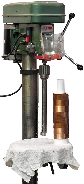
| An interesting approach
to boring The PTFE-cored coil provided by Dr Duncan Cadd (G0UTY) came with an unfinished 35 mm diameter hole bored into one end. In order to make measurements that could be compared against tubular and solid coil-former models, it was necessary to complete this hole; but with an otherwise finished item, this was not an easy problem. The length of cylinder unoccupied by conductor was not sufficient for mounting in a lathe chuck, and drills and boring bars of sufficient length were neither available nor likely to give an acceptable result. The solution was to use a 35 mm diameter Forstner woodworking bit mounted in a long extension bar; the latter being made on the lathe to give an accurate fit to the shaft. The coil was placed on the table of a pillar drill, prevented from rotating by hand (wearing a cotton glove to prevent discolouration of the copper), and the hole was gradually extended, with withdrawal of the tool after every 3 to 4 mm to remove the swarf. A flat piece of wood was placed under the coil for the final breakthrough cut. The Forstner bit is guided by a central point, and remarkably, this kept the bore true for the entire length of the coil-former. Consequently, with a final diameter of about 35.3 mm, it was possible to insert a PTFE rod of 35.0 mm diameter without further machining or adjustment. The upshot is that Forstner bits, which are available in a wide variety of sizes, are suitable for making long bores in plastic material, and have a self-guiding facility. In the example shown, the work could not be mounted in a lathe chuck, but there is no reason why the bit and extension bar cannot be mounted in a lathe tailstock. |
 |
| Effective
permittivity
of a hollow coil former The availability of a good long-hole boring method opens the possibility of making threaded coil formers with close-fitting internal sleeves and rods. This is what is needed in order to produce data on the effect of varying coil-former wall thickness. A good material for making the outer tube seems to be polypropylene; which is cheap, machinable and has a dielectric constant of 2.2 - 2.3 with a low tanδ. The dielectric constant is also very similar to that of paraffin wax (same alkane structure, shorter chain length), which can therefore be used for the inner slugs and sleeves. |
|
Ferrite rods The scattering jig lends itself perfectly well to the study of loopstick coils. Some preliminary measurements were made, but not a comprehensive study. This matter is of considerable interest because it relates to the problem of wave propagation in proximity to materials of extremely high permeability and permittivity. According to Snelling[6], the dielectric constant of Ni-Zn ferrite material is in the 10 to 40 range at radio frequencies, but the figure for Mn-Zn materials could be much higher. For such materials, dimensional resonance effects (due to the extremely low phase velocity for waves propagating in the ferrite) complicate matters greatly[7] [8]. Resonance and propagation delay measurements using Ni-Zn materials suggest that the phase velocity of the travelling wave on the helix is not greatly affected by the enormous refractive index of the ferrite. Around 0.85c is fairly typical. [6] Soft Ferrites, properties and applications, E C Snelling. 2nd ed. Butterworth 1988. ISBN 0-408-02760-6. See p127-129 [7] Determination of Mn-Zn ferrite's dimension-independent complex permeability and permittivity, Ruifeng Huang, 2008 Doctoral Thesis, Nanyang Technical Univ., School of Elec. Eng.. (Open Access: digital-repository.ntu.edu.sg/handle/10356/13336) [8] Determination of dimension-independent magnetic and dielectric properties of Mn-Zn ferrite cores and its EMI applications, R Huang, D Zhang, KJ Tseng, IEEE Trans. EMC, 50(3), Aug 2008, p597-602. |
|
Coupled resonators Drude, in his 1902 Tesla transformer paper, suggested that the overtone resonances of solenoids could be understood by imagining two separate coils magnetically coupled. This is wrong because there is no physical break between the supposedly conductively-separate sections. A current node is not the same as a physical disconnection (current waves still pass over the node, it is just that their superposition adds to zero). Two separate coils will show two separate resonances. If the coils are identical, the degenaracy of the resonace frequencies will be lifted depending on the degree of coupling, i.e., the peak will split into two peaks as the coils get closer together. It should be possible to demonstrate this effect on the scattering jig; and also to show that the double resonance disappears when the two coils make contact. The phenomenon of degeneracy lifting in identical coupled resonators is intriguingly analogous to the phenomenon of quantum-mechanical tunelling between the left and right handed forms (enantiomers) of molecules having a finite inversion barrier (see the author's PhD thesis). |
|
DWK Updated: 2016 Dec 21, 2021 May 30. |
| |
|
|
|
|