 |
 |
Screw-cutting centre lathe |
| |
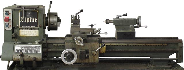
I bought this Alpine TD-5AH lathe secondhand but little used in 1989. It came with 3 and 4-jaw chucks, a surface plate, and a steady; as well as a set of metric-approximation change gears. The machine dimensions are a peculiar hybrid of inch and metric, and the screwthreads used are Whitworth. I was told by the seller that Tida made machine tools using tooling purchased from a defunct British factory, and the use of Whitworth threads seems to corroborate this.
The TD-5 is a very capable machine, and has been my workhorse for making optical instruments, underwater photographic equipment, laboratory apparatus, etc., for more than 30 years. It has allowed me to work to an accuracy of better than 0.025 mm (0.001") with no difficulty. Additional accessories I made or acquired early-on are a small toolpost grinder and drill, a milling adapter, and a simple angle finder (to be inserted into the back end of the spindle, for positioning grub-screw holes, etc.). My friend Andy Cowley also gave me several dial micrometers; which are mostly used for centring workpieces in the 4-jaw chuck. Most facing and cylindrical boring operations can be performed using a chuck or a surface plate, but the milling attachment also gave me the ability to machine linear recesses. Milling attachments mounted on the cross-slide are unfortunately, not very rigid, and so recently I bought myself a Sieg SX2P vertical mini-mill.
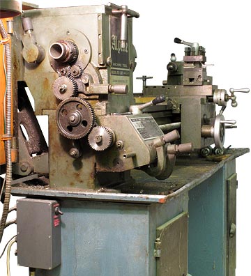 TD-5. Side door open showing gear train. |
The lathe start / stop / reverse buttons on the left in the photo above are not original. I replaced the cheap mechanically-latched button switches with contactor relays (which are in the die-cast box screwed to the steel work-table in the photo on the left). This allowed me to set up an adjustable limit-switch on the back of the machine, which is used to stop the motor at the end of a screw-cutting run. I use this arrangement because it means that I can leave the lead-screw permanently engaged during a thread-making operation. All I have to do is move the tool clear of the work using the cross slide, and reverse the machine to get the tool back ready for the next cut. I find this more reliable than using the traditional engagement-point indicator, especially since my threads are usually metric. Stopping the machine at the end of a cut, of course requires that the run ends in fresh air. Generally, I engineer things so that this occurs without intervention. |
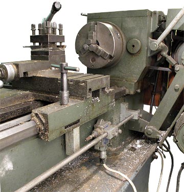
| The limit switch arrangement is shown on the right. A stub of 25 mm square aluminium bar is mounted on the underside of the carriage, and this collides with the plunger of a housed microswitch. The housing is sealed to IP67 to protect the switch from swarf and oil. The switch can be positioned anywhere on a long stainless-steel bar by loosening two knurled screws. The bar can also be released so that the switch can be turned over and installed on the other side of the actuator stub; allowing the machine to be stopped when reverse traverse or lead is used. A Forward / Reverse selector toggle on the motor relay box (covered by a rubber boot) allows either the forward or the reverse contactor to be de-latched when the limit is reached. |
|
Spindle Nose Dimensions
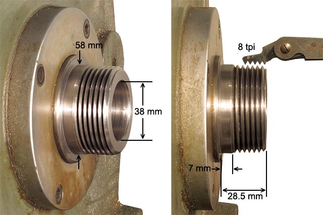
It says in the manual that the TD-4, 45 and 5 lathes have an MT5 spindle-nose taper, but this is clearly not the case for my machine because the gauge-line measurement is about 38 mm. That there is a taper however is evident by measuring the back-end of the spindle, which has an ID of 35.5 mm. Since an MT2 taper is used for the tailstock, this suggests that it is the rarely used and difficult to obtain MT4½ ( Gauge line: 38.1 mm, 1.5" ; small end: 32.156 mm, 1.266").
Screwcutting
 |
Above:
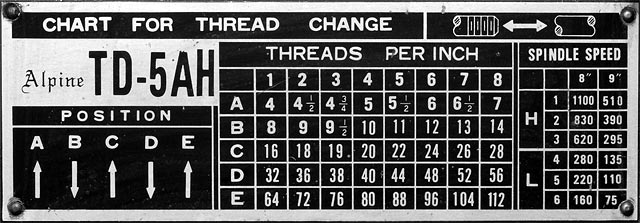
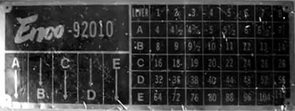
Inch screwcutting chart on the TD-5 gearbox. Left: Inch chart on the Enco 92010 for comparison. A great many lathes seem to use this traditional Norton quick-change gearbox arrangement, so the discussion below may be of general interest. |
| I note the
existence of various fora on the web where people ask about metric
screwcutting on the TD-5 and similar using the change gears. Many years
ago, I calculated all of the possible thread pitches that can be made
using this machine. What I found was that the recommended gearbox
settings were often far from optimal. Better approximations can usually
be found. Consequently, I rarely use the official settings. The full
set of available pitches (using the supplied gears) is given in the
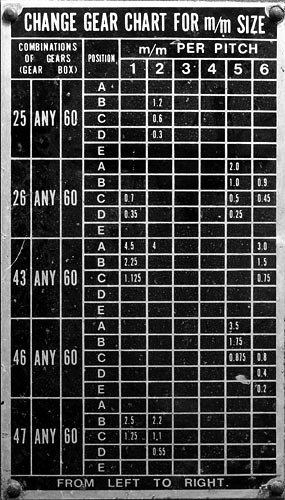
Open Document Spreadsheet: TD5_screwcutting.ods (they are ranked in order on sheet 2). This information, of course, is also required for the design and cutting of worm gears. Note for example, on the chart on the right, that for a 0.75 mm pitch (the single most important pitch for lens making) the setting {43, 60, C, 6} is recommended. The pitch you actually get with this setting is 0.758472, which is in error by +1.13%. This is bad enough to jam on long threads. The setting {46, 60, C, 7} however gives 0.748974 mm, which has an error of -0.14%. Were you to take the trouble to make a 39 tooth gear, you could use {39, 60, C, 5}, and if you were to make a 52 tooth gear you could use {52, 40, D, 5). Both of these give 0.750455, which has an error of +0.06%. |
 |
Note, incidentally, that the lead of the leadscrew is 8tpi. Thus the inch chart of the quick-change gearbox allows that the leadscrew can be rotated at up to twice the spindle speed, i.e. {40, 40, A, 1}. Due to the forces involved, rates faster than this should be used with caution, and then only when using the back gear.
 |
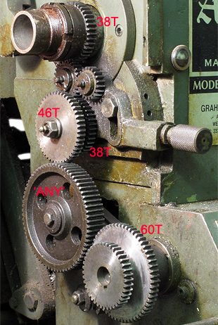 |
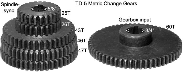
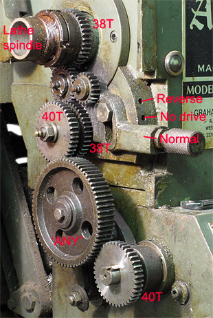
| {40, 40, . . . . } geartrain configuration used for inch screwcutting and normal tool-feed operations. The gearbox input rotates at spindle speed. | {46, 60, . . . . } geartrain, one of the configurations used for metric threads. The 40T gearbox input gear is used as a retaining collar. |
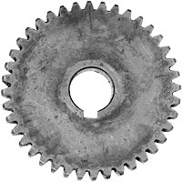 |
On the left is the TD-5 40T
spindle-synchronous change gear (the outer gear vertically below the
lathe spindle). All drive-train gears have a 16 DP involute tooth form.
The
shaft diameter is 5/8" (15.875 mm) with a 5 mm keyway. The gears are 10
mm thick and are made from what appears to be un-hardened medium-carbon
steel. The gearbox input gear has a shaft diameter of 3/4" (19.05 mm) with a 5 mm keyway. The 40T gear has a grub-screw socket, but the 60T gear does not. Hence the 40T gear is used as a retaining collar when the 60T gear is in use. |
Calculating thread pitch from gear combinations
To unravel the mysteries of the gear cutting chart, note that the first gear in the list is always synchronous with the spindle (it is not actually on the spindle, because there is also a system for selecting either one or two idler gears, so that the lead-screw rotation can be reversed). The second gear in the list is on the gearbox input shaft. In between is an idler (the ANY gear, like the Microsoft 'any key' alluded to in the phrase 'hit any key to continue'). It is also useful to note that the spindle-synchronous gear and the gearbox input gear both have 40 teeth for inch screwcutting. Because of that, we could, in principle use 40 for the second gear on the chart; but not all combinations are possible. The two small gears, 25T and 26T cannot be used with the 40T gearbox shaft gear because the idler (ANY) gear is then not big enough to span the gap (in fact, the idler and adjustment system can only just connect two 40T gears). Conversely, if you were to make spindle-synchronous gears with considerably more than 47 teeth, they might not be usable with the 60T gearbox shaft gear, because there would not be enough room. There is, incidentally, definitely not enough room for the 127 tooth gear that could give an exact inch to metric conversion. It would however be possible to make a pair of gears, 37T and 47T, giving the near-perfect conversion ratio 47/37 = 1.27027 (-0.02% error on whole, half and quarter-integer mm pitches).
A formula that gives the number of teeth per inch is as follows:
| tpi = 8 R L N |
8 is the lead (i.e., the pitch × the number of starts of of the lead screw = 8×1) ( / tpi)
R = No. of teeth on gearbox input gear / No. of teeth on spindle-sync. gear.
L = the letter gearbox ratio.
N = the number gearbox ratio
|
|
|
|
|
|
|
|
|
|
|
|
|
|
|
|
|
|
|
|
|
|
|
|
|
|
|
|
|
|
|
|
|
|
So, for example, the setting {46, 60, C, 7} discussed earlier gives:
tpi = 8 × (60/46 ) × 2 × (13/8) = 33.9130
The pitch is given by:
pitch / mm = 25.4 / tpi
so, for the above example we have;
pitch = 25.4 / 33.9130 = 0.748974 mm
error = 100 ( 0.748974 - 0.75) / 0.75 = -0.137 %
Useful Links:
Metric threading with an inch lead screw (how to avoid getting lost if you disengage the half nuts). Video by Tom Tee: https://youtu.be/D3VVyd3N72o
Thanks to Chris Case for pointing out an earlier error in my counting of gear teeth in the direction reversing system. Chris's has an interesting website detailing his toolmaking and vehicle restoration activities: Chris Case Shop Built Tools.
