| |
'Cold
Cathode' Sign Tubes
|
 |

As has been shown in the article 'inductor resonance experiments', long discharge tubes provide an effective way to demonstrate the electric field patterns around coils and radio antennas. Clear glass is also preferable to phosphor-coated glass; because it allows any discharge density variation to be seen and gives greater contrast for the location of nodes. The problem however is that the least-expensive transparent tubes are of the silica mercury-in-argon germicidal type, these being designed to maximise the hard-UV output at 254nm. Such lamps can be tamed by fitting a Lee 226 UV filter sleeve, but the need for an extra step in making the tube harmless adds temptation for the neglect of health-and-safety measures. Also, since the largest spectral component of the lamp output is not wanted, the tube is inefficient at converting RF energy into visible light.
Thus an interest in cold-cathode sign tubes; as a release from the evil basilisk glare of the low-pressure germicidal lamp, and as a move to favour tubes that are actually designed to be looked-at.
The cold-cathode tubes used in advertising signs and hoardings are commonly called "neon tubes", although only the clear-glass red-light types actually contain neon. The most widely-used fill gas is the same as in ordinary fluorescent and germicidal lamps, Hg in Ar, used either directly for its cyan colour (generally called "clear blue"); or used in tubes with internal phosphor coatings to produce a wide range of colours. The difference between the germicidal tube and the clear Hg-Ar sign tube however, is that the pressure in the sign tube is somewhat higher (causing a reduction in the hard-UV emission) and the glass is UV opaque.
In order to experiment with sign tubes, both as field indicators and out of general interest, the author had two straight tubes made by the UK signmaker Neon Creations Ltd.. These were both constructed on 60cm lengths of 15mm OD clear-glass tubing, with pre-made straight electrode assemblies giving a total inter-electrode distance of 64 cm. The electrodes used were rated for running at up to 90mA. One tube was filled with pure neon gas at a pressure of 11 mbar (8.25 Torr). The other was dosed with a few tiny drops of liquid mercury, to produce mercury vapour at saturated-vapour-pressure (SVP), and filled with Argon to 12 mbar (9 Torr). These filling details, incidentally, were decided by the tube-designer with a view to providing the best light output. The two tubes have very different strike voltages, leading to different electrical properties.
Sign tubes are normally powered using something approximating a constant-current source. They are also operated with a reasonably symmetric (non-polarised) AC waveform in order to prevent unequal electrode erosion. In early neon signs, the supply was a shunt-transformer operating at power-line frequency. This is a transformer providing several kV off-load; but engineered to have very high leakage inductance, so that it behaves as a constant-voltage source in series with a ballast inductor. Nowadays, the usual supply is an electronic constant-current inverter, operating at several tens of kHz, and giving several kV off-load.
An interesting point of relevance here is that electronic ballasts for fluorescent lamps do not use cathode pre-heating to get the tube to start. Instead they strike the tube by generating a high off-load voltage. This initiates a glow discharge that heats the thermionic cathodes and causes the starting process to complete. Thus the typical switch-on behaviour of an electronically-energised FL is that it gives a feeble steady light initially (no flickering) and then switches to full brightness about 1s later. The high-voltage starting facility means that an electronic FL ballast will start an Hg-Ar sign tube, provided that the tube is not excessively long.
The straight Hg-Ar sign tube is shown below, operating from an emergency-exit-light inverter (Type S484 - 6V DC input, push-pull transistor oscillator, ca. 30 kHz, with HV winding and 1 nF capacitor ballast).

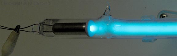
Inverter input: 6 V, 2.0 A. Running freq: 30.3 kHz.
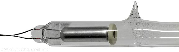
Above is a close-up of one of the tube electrodes. The term 'cold cathode' is something of a misnomer because the inside of the electrode cup is coated with thermionic emitting oxides, the surface being heated by ion bombardment in the same way as the glow-start cathode in a fluorescent tube. The term 'non-preheatable' might be more accurate, but is unlikely to catch-on. The electrode assemblies are purchased by the sign-maker pre-made, complete with glass pinch and stub tube, ready to be welded to the sign tube. The metal shell is nickel-plated iron. The ceramic guard disk crimped into the end of the cup prevents erosion of the lip (a field-emission breakdown point). The electron-emissive material coating the inside of the cup is in carbonate form when the electrode is supplied, but is converted into an oxide mixture by heating the electrode to red-heat during a part of the manufacturing process known as 'bombardment'.
In the photograph above, the black deposits and occasional shiny droplets on the inside of the tube are the mercury reservoir.
The Hg-Ar mixture has a relatively low striking voltage (about 1 kV peak for the tube discussed above). A tube filled with pure neon however is a little more difficult to illuminate. For a pressure of 8.25 Torr (mm Hg) and an electrode separation of 64cm, reference to the Paschen curve gives a breakdown voltage of about 2.1 kV (neglecting non-uniformity of the electric field). This is too high for starting with a small FL inverter; but the running voltage is only about 1 kV. Thus we might run the tube from an electronic FL ballast, but (apparently) we can't start it.
A simple solution to the starting problem is to add an external priming electrode. This will work with a high-frequency source because an electrode attached to the outside of the glass can perform the same function as an internal electrode in series with a small capacitance. Such an electrode is used in the pictures below. It consists of a thin wire, connected to the electrode at one end, then wound around the glass in a wide-spaced helix and brought close to the electrode at the other end. It is held in place temporarily by a pair of nitrile-rubber O-rings. The wire shown has the somewhat gargantuan diameter of 0.3 mm, but there is no reason why it can't be practically invisible.
The sequence below shows what happens as the input voltage to the FL inverter is varied.
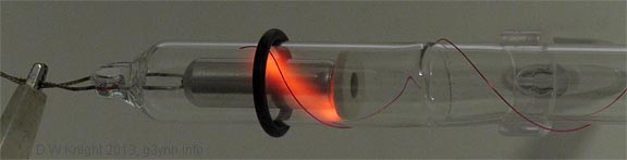
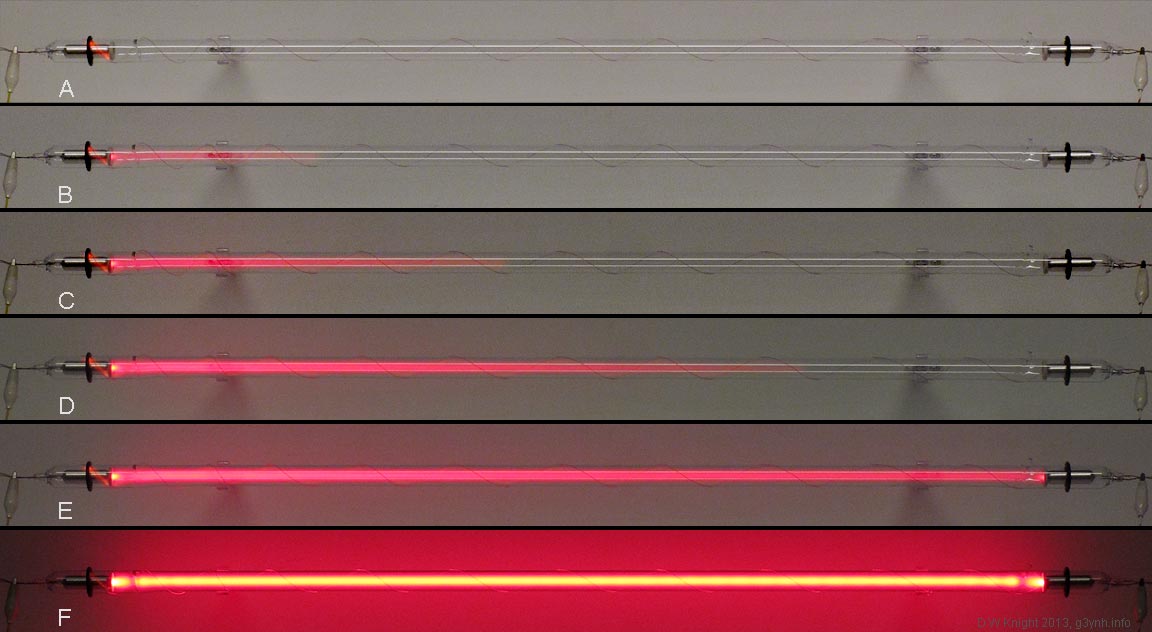
Data below are input voltage, input current and running frequency:
A: 4.0 V, 95 mA, 46.2 kHz ; A glow discharge starts between the wire and the outer electrode shell.
B: 3.7 V, 125 mA, 45.7 kHz ; Increasing the voltage starts a discharge between the wire and the electrode interior. The voltage needed to sustain this discharge is less than the voltage required to start the initial glow.
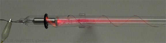
C: 4.4 V, 0.19 A, 45.1 kHz ;
D: 4.9 V, 0.24 A, 44.7 kHz ;
E: 5.6 V, 0.31 A, 44.5 kHz ;
F: 6.0 V, 1.8 A, 36.9 kHz ; Both electrodes produce thermionic electrons, and the transition from glow discharge to arc occurs. Notice the enormous jump in the inverter input current from E to F.
To get a crude idea of the inverter output voltage, note that the inverter uses a pair of BCU83 NPN transistors in push-pull configuratuin. These have a nominal saturation voltage of 0.5V, so the voltage switched across the transformer primary will be approximately Vin - 0.5. Therefore, the output will be approximately:
Vout = Vmax (Vin - 0.5) / (6 - 0.5)
Vmax is about 1 kV peak (for 6V DC in).
Neon Sign making at Neon Creations.
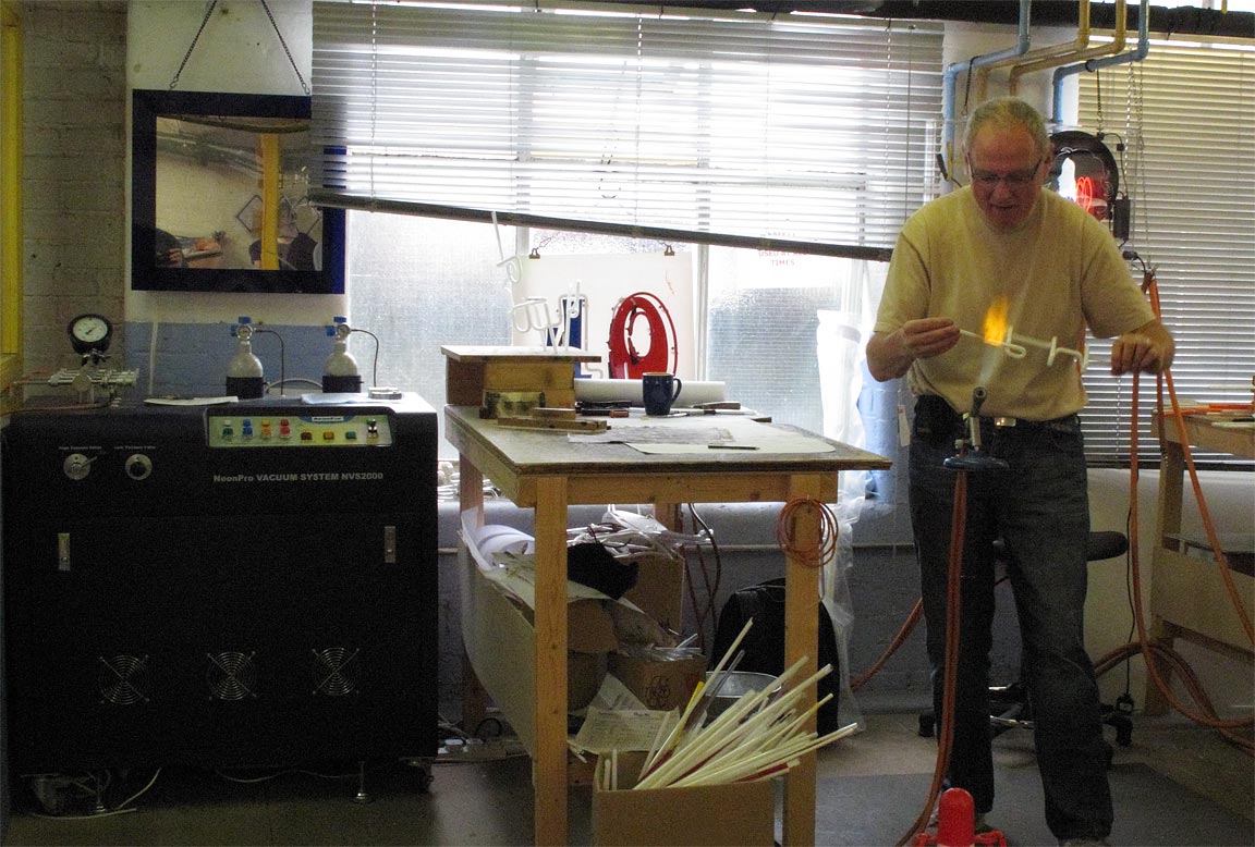
On the left in the picture is the vacuum pumping system (NeonPro NVS2000) with gas dosing manifold and cylinders of neon and argon. In the process of being bent, and in the box in the foreground, are tubes with internal phosphor coating. These fluoresce when irradiated with UV light from the Hg-Ar discharge and produce colours other than cyan-blue and red. (Photo DWK, 2013 Sept 13th)
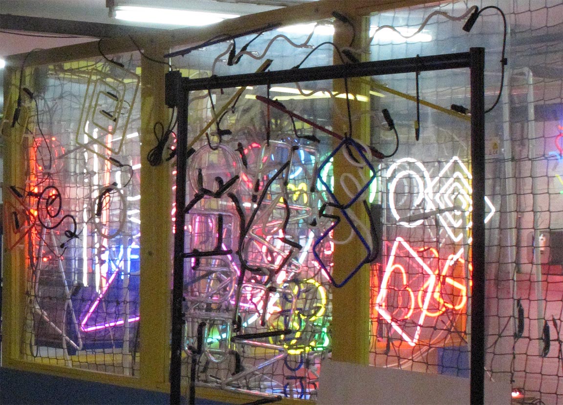
Pumped, bombarded, filled and sealed. In the background the tubes are illuminated for 'ageing in'. In the forground are tubes with block-out paint applied to create dark regions (between letters, etc.). (Photo DWK, 2013 Sept 13th)
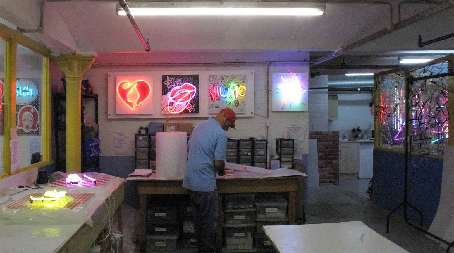
Final test and dispatch (Photo DWK 2013 Sept 13th)
| Links: |
| |
|
|
Tube PSUs |
|
© D. W. Knight, 2013, 2021
Last edited: 2021 Aug 1st .
