|
|
|
|
|
|
Variable Inductors
the various types and their properties
by David W Knight
|
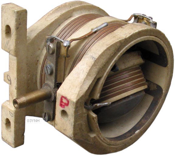
Variometers A variometer is a pair of coils arranged in such a way that the axis of one can be rotated relative to the axis of the other. The coils are usually wired in series, and rotating one of the coils alters the mutual inductance. When the magnetic fields produced by the coils are in full or partial opposition, inductance cancellation occurs (mutual inductance is negative). When the fields add, the inductance increases (mutual inductance is positive). The mutual inductance is zero when the axes of the two coils are at right angles. The principal disadvantage of using a variometer as a variable inductance is that the conductor length remains constant as the inductance is altered. This means that the RF resistance is unnecessarily high for small inductances; i.e., the Q is poor at the low inductance end of the range. The fixed conductor length also gives rise to a lower than necessary self-resonance frequency (SRF) for a small inductance setting, i.e. the useful frequency range is limited. Self-resonance in an isolated coil occurs when the total conductor length is λ0/2 or less (estimates using c as the propagation velocity are usually accurate to within a few % for simple solenoids, but in variometers, the SRF is reduced by the stray capacitance from coil to coil). A variometer should not be used at frequencies approaching its open-circuit SRF. Due to the electrical shortcomings discussed above, the use of a variometer as a wide-range variable inductor is not good practice. An acceptable application is supplemental fine inductance adjustment, provided that the variometer inductance is a small part of the total. Variometers are also useful (with the coils wired separately) in applications that require variable coupling between different parts of a network (e.g., for injecting balancing signals in some types of measuring bridge). |
|
|
|
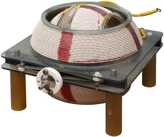
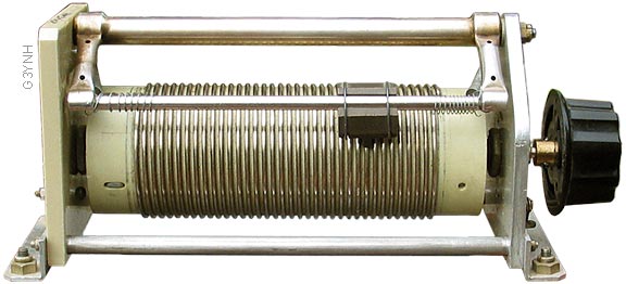
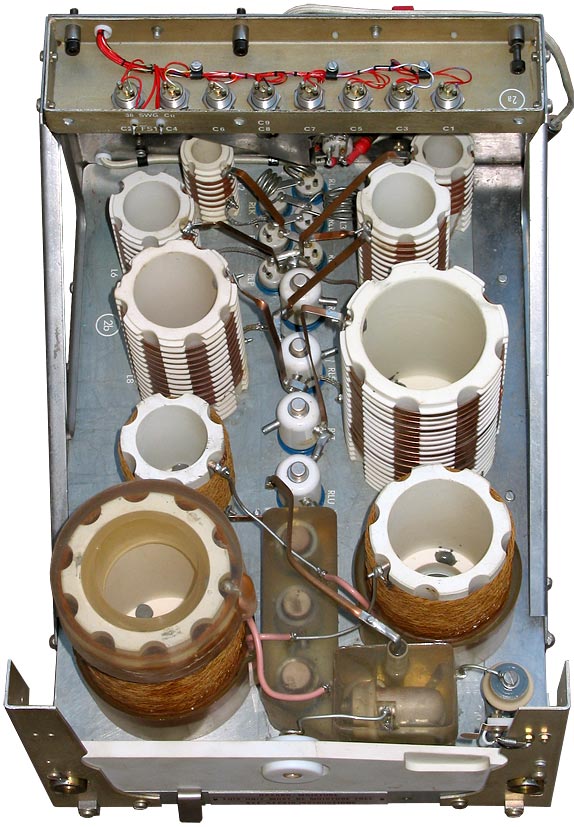
Roller Inductors The roller inductor (known in the vernacular as a "roller coaster") has the advantage that the conductor length reduces as the inductance is reduced. This keeps the RF resistance of the coil at its practical minimum and allows reasonably high Q to be maintained at the low end of the inductance range. The big disadvantage of the roller inductor lies in the fact that the unused turns are magnetically coupled to the turns in use. If N is the number of unused turns, and r is the radius of the coil, the length of the unused winding is approximately 2πrN. If the unused winding is left open-circuit, a high voltage is developed across the redundant section when the electrical length of its winding is λ/2 at the frequency of operation. The resulting corona discharge is likely to etch the wire and blacken or damage the coil former. One solution to the corona discharge problem is to short the unused winding. This however, gives rise to a large circulating current that reduces the inductance substantially. It also factors the resistive losses of the unused winding into the overall losses, and reduces the Q considerably. |
|
|
|
|
|
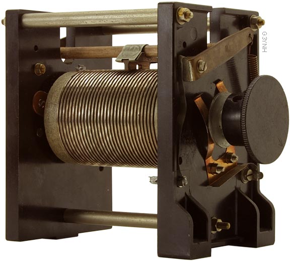
Helipot Inductors. Some variable inductors have a stationary coil and an internal wiper arm, i.e., they use the same mechanical arrangement as a helical potentiometer. These devices do not appear to have a proper name. They are called "roller inductors", even though they are not (except in the sense that a rolling contact may be used for the wiper). To avoid confusion, they will be referred to here as "helipot inductors". Helipot inductors have the advantage that they do not require brush contacts for the coil end connections. Hence the ESR should be slightly lower (or at least more consistent) than that of a roller inductor of comparable geometry. Another advantage is the absence of a ceramic (or worse still, phenolic-paper composite) coil former. |
|
|
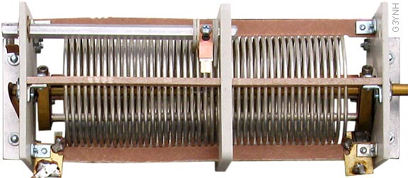
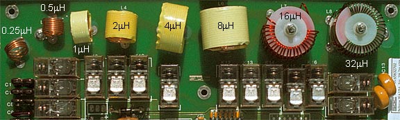
Binary Switched Inductors When two or more inductors are placed in series and arranged in such a way that there is minimal mutual inductance between the separate coils, the inductances simply add. By shorting out individual coils by means of relays, a stepwise variable inductance can be created. By choosing the component inductances according to a binary sequence, the relay drivers may be connected directly to a data register and operated by a microcontroller using the simplest possible program. The disadvantage of the switched inductor chain is that the degree of mutual inductance used in producing a given inductance is sub-optimal in terms of Q and SRF when more than one coil is in circuit, i.e., the same amount of inductance could have been produced with a shorter length of wire. The conductor length drawback is however, nowhere near as severe as with a variometer, because (in impedance matching applications at least) the larger inductors are not used at the high frequency end of the operating range. |
|
|
|
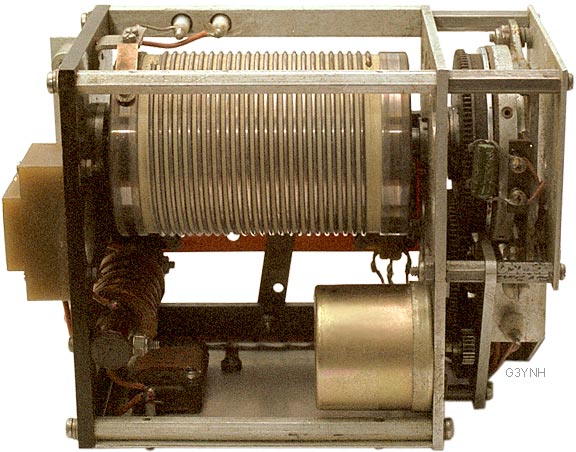
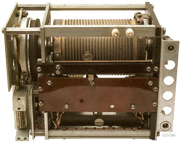
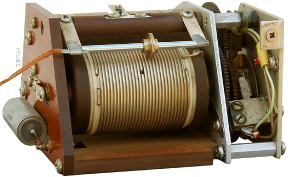
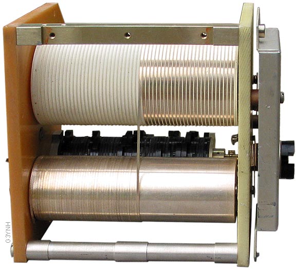
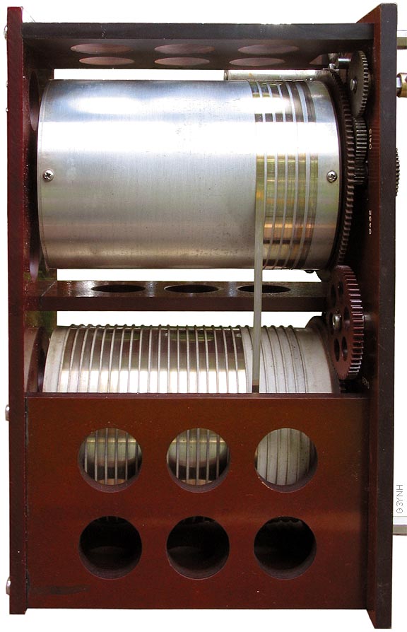
Coil and Capstan The coil and shorting drum is the 'no compromises' solution to the problem of designing a variable inductor. For any setting, the inductance always has the shortest possible conductor length and hence the highest possible Q and SRF within the constraints of the chosen geometry. The downside is complexity. The rotation of the two cylinders must be synchronised using gears, and the conductor must be tensioned (usually by means of a clock-spring inside the shorting drum). An elaborate end-stop system is needed, since the device will fail if either drum is repeatedly unwound as far as the end connection. Notice also that, in order to avoid failure due to metal-fatigue, the drum diameters must be chosen according to the conductor thickness and hardness in such a way that the conductor experiences minimal plastic deformation (i.e. the winding and unwinding process must depend principally on the spring-like nature, rather than the plasticity, of the metal strip). Hence the conductor base (beneath the silver plating) is made from thin brass or hard copper. |
|
|
Text and photogtaphs © D W Knight 2007-2013
David Knight asserts the right to be recognised as the author of this work.
|
|
|
|
|
|