| |
|
|
|
and its use in a balanced antenna configuration (An All-band HF antenna system for difficult EMC environments) by David Knight ™ 'Smartuner' is a registered trademark of SGC Inc. |
| Given the enormous amount of
domestic electronic equipment now in service, anyone attempting to
set-up a short-wave transmitting installation at home is almost certain
to experience EMC problems. This is particularly the case for those who
attempt to drive a wire antenna against an earth stake, the reason
being that the house wiring, being more conductive than soil, acts as a
parasitic ground plane. The domestic house must now be regarded as one of the most difficult of environments from an EMC point of view; containing both sources of HF noise and devices susceptible to HF interference. Any voltages or currents induced in the house wiring by a radio transmitter are likely to cause problems, especially with Hi-Fi systems, burglar alarms and computers. Reciprocally, if the mains wiring forms a parasitic component of the antenna system (the earth is part of the antenna after all) then any mains powered device with an oscillator in it is likely to cause reception interference. Radio operators often spend large amounts of time trying to resolve such issues on a case by case basis, but this is at best a war of attrition when new devices can be introduced at any time. The definitive solution is to use an antenna that does not require an earth, to place that antenna clear of the building, and to force the feedline currents to be equal and opposite so that the feedline can neither radiate nor receive radio signals. The simplest HF antenna associated with best EMC practice is the centre-fed wire dipole (or doublet) used in conjunction with one or more balun transformers. The ease of integration into a domestic environment accounts for its popularity, but a failure to appreciate the capabilities of the basic device has given rise to a literature filled with misleading suggestions on the subject of how best to use it. Introductory material recommends that the dipole should be made one half-wavelength long, so that it can be connected directly to a transceiver antenna socket; but that gives rise to a system that will only work on a single amateur band (or part thereof) and leads to the belief that anyone who wants to operate on 160 m must have a garden at least 80 m long. Specific recommendations for improving upon this highly restrictive situation are then; the introduction of traps, which permit operation on more than one band but are lossy and difficult to adjust; or worse still, the inclusion of some magic length of twin-wire line between the antenna and a co-axial cable feeder. The latter type of antenna, widely available as a commercial product, generally gives a rather poor impedance match on several bands and relies on the losses in a length of cheap 50 Ω cable to achieve an acceptable SWR. It is always possible to obtain broadband performance by introducing resistive losses, but such devices are better classified as patio heaters than as antennas. The reality of the dipole antenna is that it does not need to be operated at resonance. Furthermore, any wire longer than about 25 m can be used for international communication throughout the entire HF range (160 m included). All that is required to realise this phenomenal versatility is a matching network (an ATU or AMU) to cancel the antenna reactance and transform the input resistance to match the transmitter's preferred load. The standard method for operating a dipole antenna on all HF bands is to feed it with open-wire line ("ladder line") and connect it to an ATU situated next to the transmitter. Note that a wide-range ATU is required. The antenna tuners built-in to some transceivers are designed only to correct for slightly mismatched co-axial feeders and are not intended for this application. The ladder line usually had a characteristic impedance in the 400 Ω to 600 Ω range and will necessarily operate with very high SWR at some frequencies. The severe mismatch does not matter however, provided that the wire is made from high-conductivity material (e.g., silver-plated copper) and provided that low-loss dielectrics are used for any insulating materials. |
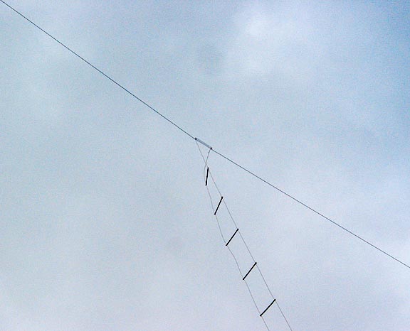
| There are certain drawbacks to the
use of antenna tuners however, which may be listed as follows: |
| The way to eliminate the tedious
and tricky business of matching the antenna every time the frequency is
changed is to use an automatic ATU. Various models are now available,
but when this work was started, the most popular item aimed at the
amateur market was the SGC-230. The author therefore decided to set up
an electrically symmetric antenna system based on the SGC-230, and by
taking certain liberties with the instructions in the user manual, was
able to eliminate the ladder-line and place the balun at the input side
of the matching network. SGC-230 Technical Description: The SGC-230 'Smartuner' is an automatically tuned π/L-network. There are various models in the 'Smartuner' family (see the SGC website), but the 1.6 MHz - 30 MHz SGC-230 is nominally rated for 200 W PEP and is therefore ideal for use with typical 100 W HF transceivers. A view of the SGC-230, with its cover removed, is given below: |
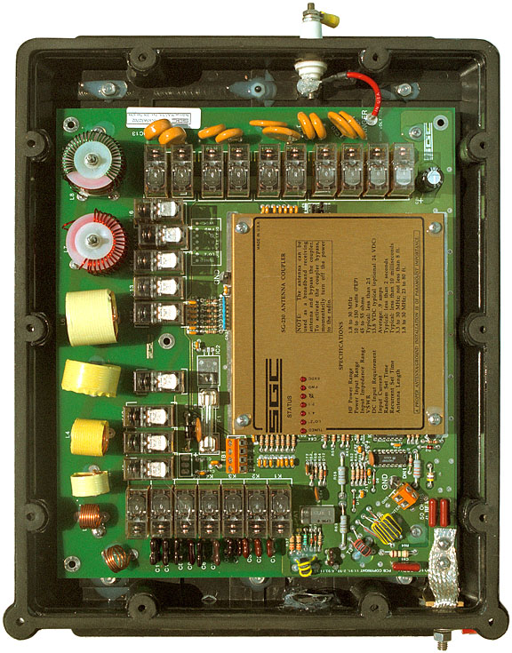
| Instead of using continuously variable tuning elements, the SGC antenna coupler uses relay-switched capacitors and coils, which are selectable in binary increments. The input (TX side) capacitors and relays are at the bottom in the picture above, the coils are on the left, and the output capacitors are at the top. Note that the coils are arranged to minimise the magnetic coupling between them, so that they may be selected without errors due to mutual inductance. Note also, that the output capacitors are switched by pairs of relay contacts in series (hence 10 relays for 5 values), this being done to reduce the risk of flashover when attempting to drive high impedance loads. The antenna terminal is the high-voltage insulator at the top of the box. The earth terminal is the braid at the bottom right. The input 50 Ω co-ax. line from the transmitter goes to the small orange barrier strip close to the earth terminal (the supplied connecting cable has been removed in this photograph). The available tuning element values are summarised in the table below. |
| Tuning element | Values | Step Size | Max combined |
| TX side | 0, 100, 200, 400, 800, 1600, 3200 pF | 100 pF | 6300 pF |
| Inductor | 0, 0.25, 0.5, 1, 2, 4, 8, 16, 32 μH | 0.25 μH | 63.75 μH |
| Antenna Side | 0, 25, 50, 100, 200, 400 pF | 25 pF | 775 pF |
| The inductors are numbered L1 - L8
in increasing value. The two large value inductors L7 (16 μH)
and L8 (32 μH) are each wound on two stacked red toroidal cores.
Two stacked identical cores have twice the AL
value of a single core. If we guess that the cores are Amidon
(Micrometals) type T-157-2 (Carbonyl iron, μi=10, AL=14 nH/turn²); L7, which
has 24 turns, has an estimated inductance of 24²×28
nH=16.1 μH, and L8, with 34 turns, has an estimated inductance
of 34²×28 nH=32.4 μH. We can therefore be
reasonably confident of the core type, in which case, the Amidon data
would lead us to expect an unloaded Q of around 300-360 for these
coils. Such surprisingly high Q values promise good efficiency at low
frequencies. From the step-sizes used, the matching unit might first appear to offer a rather coarse-grained solution to the problem of tuning up; until we note that the device offers some 219 (i.e., 524288) possible element combinations. The coupler is operated by a 6805 microcontroller. The processor clock crystal is on the NTSC colour subcarrier frequency of 3.579545 MHz; which lies in the 80 m amateur band; but no reception interference is caused because the clock is turned off in the absence an of RF input from the transmitter. Tuning is accomplished by sampling the following quantities: Input Frequency, Forward and Reflected Power, Input Impedance (V/I), and Input Reactance (V - I phase difference, φ). The RF detector section of the unit is shown below: |
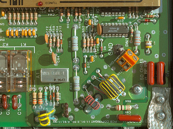
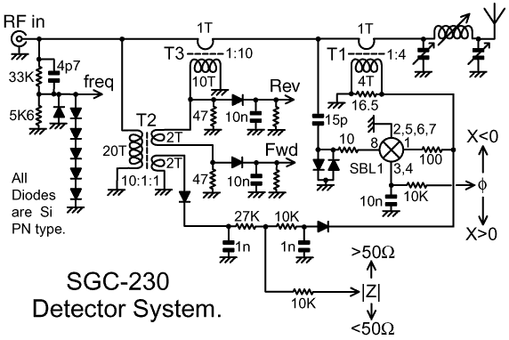
| Outputs from current transformer T1 and voltage transformer T2 are rectified and combined to form an impedance bridge, which is balanced for 0 V output when the impedance looking into the antenna coupler is 50 Ω. T1 current sample, and a limited voltage sample from the line are also combined in a Mini-Circuits SBL-1 double-balanced mixer, to form a phase bridge which gives 0 V output when the input to the coupler presents a resistive load. Positive going signals proportional to forward and reflected power are obtained from a directional coupler comprising T2 and T3. Frequency is sampled by limiting the signal from the line and applying it directly to the ripple-clock input of a 74LS93 counter. |
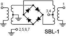 Mini-Circuits SBL-1 |
| Stripped of the output for the phase and resistance bridges, the directional coupler is an implementation of the Sontheimer-Fredrick type 9 bridge configuration [as used by John Grebenkemper KI6WX in his directional wattmeter article in QST, Jan 1987. See also ARRL Antenna Book, 19th Edn 2000, ISBN 0-87259-804-7 "The Tandem Match" ch 27, pp9-19]. |
| The tuner has a non-volatile
memory in which it stores tuning solutions as a function of frequency.
When forward power is detected for the first time after powering-up, it
sets the tuning relays according to the data in memory for the current
frequency and then checks the SWR. If the SWR is less than 2:1, the
'tuned' line on the control cable (see below) goes low and the
processor halts. If the SWR is greater than 2:1, the control program
branches to the 're-tune' routine; the object of the exercise being to
cancel the reactance of the antenna and choose inductance and
capacitance values which effect the required impedance transformation.
If the re-tuning is a success, the 'tuned' line goes low, the new
solution is stored in memory, and the processor halts. On the next
transmission, the processor awakes briefly to see if the frequency has
changed or if the SWR has risen above 2:1, and goes back to sleep if
they have not. In this way, the unit learns the required tuning element
values for a particular antenna at a particular frequency. If a good
solution has been found previously, the tuning process takes about 20
ms, which is the time it takes to determine the frequency and close the
appropriate relays. If re-tuning is required, the process can take up
to about 3 s as the unit steps through its inductor and capacitor
values; resulting in an initially high SWR on the line from the
transmitter, which rapidly drops as a solution is approached. SGC
claims that the unit will usually produce an SWR of better than 2:1 on
all frequencies for which a tuning solution exists. In practice, in the
author's installation, it usually achieved an SWR of better than 1.7:1
in the working range 1.81 MHz to 29.7 MHz, giving reasonably
stress-free operating conditions for the transmitter PA (but how much
of the energy is radiated is another matter). Since some transmitters
will start to reduce power at about 1.4:1 SWR, it is preferable to use
a transceiver with a built-in restricted-range ATU (known colloquially
a "line flattener"), to ensure that the transmitter always sees an
ideal load and gives maximum output with low intermodulation.. It takes about 3 W of forward power to activate the automatic tuning system. Clearly there will be some insertion loss due to the two current transformers in the line, but is not an issue in normal circumstances. The presence of various limiting diodes and magnetic transformer cores however has implications with regard to receiver performance: in that non-linear devices in the antenna system may give rise to cross-modulation and harmonic generation from strong nearby transmitters. No data are available regarding the tuner's performance in this respect, but it was noticed by the author that the second harmonic of a nearby amateur station ("400 W" on 14 MHz, at a distance of 2 km) was enhanced in comparison to the signal from a simple wire receiving antenna. The interface cable to the SGC 230 consists of a single sheath containing the RG58 feed-line and four wires: +13.8 V, 0 V, 'Tuned' and 'Reset / Lock' (in the original manual, the 'Tuned' line was called 'Tune', but this is a misnomer since its purpose is to indicate that the tuning process has been completed). In a minimal configuration, it is only necessary to feed RF into the line, which is supplied fitted with a PL259 plug, and connect the 13.8 V supply. The basic model has no provision for tuning-up in the absence of a transmitter, and so the unit is not ideal for short-wave listening. A balanced antenna based on the SGC-230: The only real disadvantage of the SGC-230 from the author's point of view, is that it is not designed for use with balanced antennas. The use of a balun transformer on the feeder to a non-resonant antenna is also non-optimal, and SGC specifically advises against doing so when using the SGC-230. The tuner however, does not need a ground reference in order to work; and so it is perfectly sensible to suppress common-mode feeder currents by winding the input feed-line and the power / control cable together into a choke balun. The author's first attempt at such an installation was successful, and is shown below: |
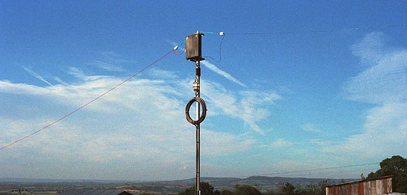
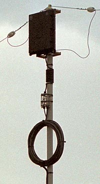
| The tuner was mounted at the top of a 2.5 m fibreglass pole, which was clamped by means of a straight-coupler to a standard 2" diameter aluminium mast. One side of the dipole went to the antenna terminal, and the other side went to the earth terminal. The arrangement, although physically asymmetric, is electrically symmetric due to the action of the choke balun. The cable supplied with the tuner was wound around the fibreglass pole (13 turns) and brought to a junction box, which was made from an old underwater light meter housing fitted with three IP68 cable glands. Inside the junction box, the RG58 feedline was connected to an RG213 cable from the transmitter (the original PL259 plug was connected to an SO239 free socket) and the power and control wires were connected to a 4-core shielded cable rated at 7 A (the current consumption of the SGC230 is less than 1 A, but a decent cable is needed to avoid voltage loss on long runs). By leaving the supplied cable intact (feeding it through the junction box gland from the inside and then reconnecting it to the tuner) the tuner can be restored to its factory supplied condition if necessary, but care is needed in re-sealing the weatherproof enclosure properly. |
 |
|
The junction box was
separable into two parts, with the cables from the house attached to
the cover-plate and the cable from the tuner attached the box, so that
the tuner could be disconnected easily for service. To make the main
choke balun, the two cables from the junction box were taped together
at intervals and then wound together into a flat 10-turn coil of about
40 cm diameter, which was held together with black UV resistant cable
ties. Down from the mast, the two cables entered the house through a
soffit vent, and were coiled into yet another choke (this time 5-turns)
in the attic-space, before passing into the radio-room. Total length of
the RG213 feed-line, including the chokes, was 39.8 m. The fact that
the installation worked first-time (as expected) indicates that the
exact details of the choke balun arrangement are not critical. Note
however, that the large balun coil will have a low self-resonance
frequency, and the smaller coil above provides backup in the event that
the large balun should exhibit parallel resonance. The arms of the author's first dipole were each 17 m long, with a 1 m gap between the insulators at the feed-point, to give a total length of slightly more than 35 m, with a measured resonance at 3.9 MHz. |
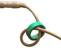
| EMC Issues: On commissioning the antenna, tests were made to see if the SGC-230 could tune-up the antenna on all traditional and WARC bands, as indeed it could, and to see what EMC problems would result. Surprisingly, given the intractable difficulties encountered on trying to use an end-fed antenna, the only immediate problem was that of one computer; which flagged a keyboard buffer over-run error and promptly crashed when a signal was emitted on 40 m. This was a radiated interference problem. The computer in question had an unusually long coiled keyboard cable, which was probably resonant on 7 MHz. A ferrite ring at the keyboard socket (right) eliminated the trouble. |
 |
| Otherwise, the choke-balun arrangement was so effective at keeping RF out of the mains, that a Maplin mains intercom system (120 KHz FM), which had previously emitted loud un-demodulated SSB noises when an end-fed antenna was used, became usable while the transmitter was running. The house burglar alarm system however, retained a tendency give a tamper alert when signals were transmitted on frequencies of 7 MHz and above; but the problem could be eliminated by putting the alarm into 'engineer' mode. |
| Performance: As far as propagation characteristics are concerned, the antenna system described is suitable for NVIS (near-vertical-incidence sky-wave) communications at low frequencies, moving gradually to lower-angles as the frequency is increased; the frequency at which the low-angle radiation becomes useful being a function of the height, particularly at the feed point. In the author's original configuration, the feed point was only some 12 m above ground, and only 7.5 m above the flat roof of an annex building. Using a 100 W PEP transmitter, G3YNH (near Exeter, in Devon) received signal reports of 59+ from all over the British Isles and Western Europe on 40 m and 80 m. On 160 m, where the antenna is electrically short and the system less efficient, 59 reports appeared to be confined to a radius of a 350 - 500 km, depending on atmospheric conditions, but perfectly good 58-59 QSOs were had with stations in northern Scotland (about 1100 km). The author's location is approximately 550 ft ASL, with a good take-off to the West, and nightly transatlantic 57-59 contacts could be made without difficulty on 20 m. Long-path VK QSOs under suitable conditions elicited signal reports of 56-57. Later changes to the arrangement of support masts raised the average height of the antenna to 15 m. This modification increased transatlantic signal reports on 20 m by about 12dB, and elicited 59+ reports from Canada on 80 m (under suitable conditions). The antenna therefore proved itself to be a very acceptable all-rounder, but was, of course, no substitute for an HF beam. Note that on higher frequencies, the antenna described is effectively a centre-fed long-wire. This means that the radiation pattern breaks up into multiple lobes, with gain in some directions and nulls in others. In the authors's installation. with the wire running on a bearing of 110°, signal reports gave evidence of a null in the direction of central USA on 17 m and 20 m. Such nulls are a fact of life with long-wire antennas and, if possible, should be taken into consideration when choosing the orientation of the wire. One drawback with the antenna system as described was its poor performance on receive on some bands until a carrier had been sent to the SGC-230 to make it tune-up. This was entirely the author's fault, for using 40 m of feed-line contrary to the recommendations in the manual; but was also a necessary consequence of using a choke balun. The attenuation was not serious on frequencies close to odd-order resonances (i.e., on 80 m and 20 m), but was significant on frequencies close to even-order resonances (i.e., on 40 m and 10 m). The difference in received signal level between tuned and untuned states on 40 m was about 30 dB. One short press of the Morse key would bring the antenna to life, but there was no proper provision for listening outside of the amateur bands. In practice however, due to the high noise levels on the HF bands, the lack of receive sensitivity in the untuned condition was rarely a problem. |
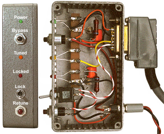
| Control Box: In addition to receiver desensitisation when the antenna is untuned, there may also be encountered frequencies on which the tuner has difficulty in finding a unique tuning solution. If this occurs, the tuner will keep on trying to retune during the course of an SSB transmission, and thereby disrupt station operation. The problem occasionally cropped up on 160 m in the installation described above. SGC is aware of it, and has provided a solution in the form of the 'reset / lock' control line (revision T onwards), which can be tied to the +13.8 V supply to prevent retuning. Access to this functionality can be had by purchasing the optional 'Smartlock' unit, or equally well by building the simple control box shown below: |
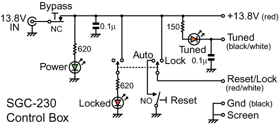
(Legend: NO = Normally Open, NC = Normally Closed)
| The SGC-230 must be supplied with
power even when receiving on an untuned antenna, because it powers-down
with all of the inductors in series with the antenna. At power-on, all
tuning elements are removed until the first transmission, and so the
bypass button allows this condition to be achieved without turning off
the PSU (which, to avoid earth loops, should preferably be the same as
the one used by the transceiver). Tuning, or retuning, is prevented by
moving the switch to the 'Lock' position; while pressing the 'Retune'
button in the auto position forces the coupler drop all tuning elements
and retune on the next transmission. It might appear, from this, that
the 'retune' and 'bypass' buttons perform the same function; but the
'retune' button forces the tuner to branch to the 'retune' routine
regardless of the data in memory, whereas the 'bypass' button allows
the tuning to be taken from memory when possible. It is useful to be
able to drop all tuning elements when changing bands, and using the
bypass button enables retuning to take place in the shortest possible
time after having done so. Note that the 'Tuned' LED has a series
resistor of 150 Ω, while the other LEDs have 620 Ω
(for approx. 20 mA @ 13.8 V). This is because the 'Tuned' line already
has 470 Ω in series with it inside the coupler unit. In the
author's installation, an additional high-brightness 'Tuned' LED with a
680 Ω series resistor was placed inside the clear junction
box on the mast; the idea being that the LED in the control box, with
its much lower series resistance, would steal current from it and
prevent it from lighting once the control box was built. In practice,
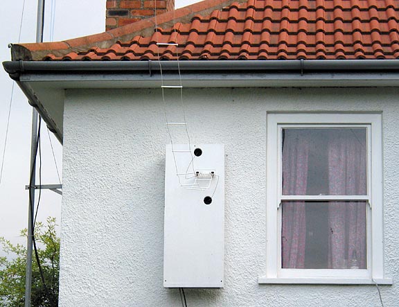
the LED in the junction box continued to work. Additional Notes: The UK retail price of the SGC-230 in June 2002 was £369. While this might seem like a substantial investment; it is worth noting that it would cost about as much to buy the components required (don't forget the weatherproof housing), and it is difficult to imagine a more straightforward solution to the problem of how to radiate on all HF bands. Were I to build this installation again, I would try a W2DU ferrite bead balun (see references below), installing small ferrite rings on the composite cable supplied with the tuner. A W1JR-type toroidal cored balun is probably a better choice when using thin coax, but the cable in this case is too thick to be wound around a small toroid, and a large core, having a longer magnetic path, might not provide sufficient choking inductance on 160m. The change to a W2DU balun would reduce the length and losses of the feed line, reduce the weight and windage on the mast, and improve the aesthetics of the installation. Calculated losses for the 40 m of RG213 feedline were 1.03 dB at 14 MHz for 1:1 VSWR. For 2:1 VSWR at 14 MHz, feedline losses increase to about 1.5 dB. Conductors for antennas and feedlines should be made from plain copper, enamelled copper, or silver-plated copper. Aluminium is also suitable, but aluminiun to copper junctions must not be exposed to rain. Silvered conductors must be coated to prevent sulphide formation. Other materials have high resistivity and should not be used in RF power transmission applications. In many installations, the tuner and dipole may work perfectly well with no balun whatsoever. In this case, there may be some radiation from the feed line, but this is largely irrelevant in the absence of EMC implications. The balun however, guarantees good behaviour and makes the success of a first-time installation more likely. The installation described above was dismantled in May 2002 and the equipment passed to Andy Cowley* M1EBV in Bristol. Reasons for dismantling the system were not due to dissatisfaction with its performance, but due to a desire to increase transmitter power to the UK legal limit (400 W PEP). When the SGC-230 housing was opened after 18 months on the mast, the interior was found to be completely dry and pristine; although it should be noted that during the period of use the 12 V supply was always left on, so that the 9 W or so of static power dissipation would help to prevent internal condensation. Andy's installation is shown below. The SGC-230 and the choke balun were hidden inside a wooden box, and the antenna was fed with ladder-line. The antenna and the ladder line were made from 19 × 0.2 mm silver-plated ETFE coated wire. The antenna was 34 m long , with an average height of about 12 m. Even with about 10 m of ladder line (115 mm spacing, PTFE insulators) the antenna gave almost identical performance to that obtained by the author using about the same length of dipole at the same height (average S7 to S9 between Bristol and Aberdeen on 160 m). The only problem experienced was that the line had to be pruned in order to enable the SGC-230 to find a match on all HF amateur bands. |
| © D.W.Knight G3YNH,
Original November 2000. Updated Jan. 2007. 9th Aug. 2013. David Knight asserts the right to be recognised as the author of this work. * Sadly, Andy died in April 2012, aged 64. |
|
|
| 1) Input impedance of centre-fed dipoles, ch 2, p2-6 2) KI6WX Directional Wattmeter: "The Tandem Match" ch 27, pp9-19. 3) Ferrite bead balun: "The W2DU Balun" ch 26, p21-23. CQ Communications 1994. ISBN 0-943016-09-6. Chapter 1 on the 1:1 Balun is highly recommended. Book is available from Amidon Associates:. |
| |
|
|