 |
E-bike conversion |
E-bike Legal |
E-bike battery |
E-bike electrics |
Side stand |
Steering damper |
Electric m/c |
EAPC Lighting & Electrics
Improving e-bike ergonomics and safety by adding standard motorcycle lighting equipment and other electrics.
Brake switches
Commercially produced e-bikes are required to have motor kill switches, which operate when the brake levers are pulled. For those who build their own e-bikes however, this functionality is optional, and also sometimes difficult to implement. The Bafang BBS01 and 02 mid-drive kits, for example, are supplied with replacement brake levers that have switches; but those levers only work with cable-operated brakes. For those who have hydraulic brakes, there are magnetically-operated switches that can be bought separately; but the parts attach to the brake levers using adhesive pads, and many levers have no flat surfaces on which to stick things. Also, the resulting open magnetic circuit has a large compass-safe distance (>0.5 m), which precludes mounting a compass on the handlebars. Finally, there are hydraulic brake systems designed for the e-bike market, with switches built-into the levers (such as the Tektro Auriga E-comp); but having to replace the brakes on an existing bike is expensive and requires considerable work, and the switches are also usually magnetic.
Given the difficulties, the lazy solution to the kill-switch problem is simply not to use them. They are designed to be open-circuit until the brake is applied, and so it is not necessary to plug them in to the motor wiring harness. There are then however, many situations in which it takes the motor controller several tenths of a second to realise that power output should cease; and in those instances, the unwanted energy must be dissipated in the brakes. This effect is not necessarily serious, but it does imply a degradation of stopping distance, unnecessary brake-pad wear, and a small extra drain on the battery.
As stated in the parent article, the author has two e-bikes; one based on a Forme Sterndale with 27.5" wheels, and the other based on a Saracen Tufftrax 29. Both of these have hydraulic brakes, with levers that lack anywhere to put stick-on magnetic switches. It was my firm intention however to fit switches somehow; not only for the motor-cutoff function, but because, apart from legislative inertia, it is hard to think of a reason for excusing e-bikes from having brake lights.
The Saracen 29 has Tektro Auriga brakes that have an M4 reach adjustment screw on the brake lever. It can also be observed that some Tektro levers, such as the Orion SL and Auriga Pro, have a reach adjustment screw with a large knurled head; which suggests that a longer screw might be used without interfering with the rider's natural hand position. I therefore fitted longer screws with locknuts, the point being that the protruding part might be then used for attachment of some kind of linkage, and rode the bike like that for a while to see if there was any ergonomic downside. I found that I was completely unaware of the non-standard screws, and so started to consider how I might make use of them.
My first thought was to try to fit spring-loaded or pull-operated switches to the brake lever bodies. There is however nowhere obvious to attach anything; except perhaps for a tapered region next to the hydraulic hose connection, and a simple clamp attached at that point is unlikely to grip reliably. It goes without saying of course, that after a long career in engineering, I have a strong aversion to sticky pads (perhaps they have improved, but all of the ones I have ever used disintegrated after a year or so). It seemed therefore, that I would need to develop complicated mouldings to fit around the brake-lever bodies and give mounting points for waterproof micro switches, and that I would probably need to disconnect the hydraulic hoses in the process of fitting them. In such circumstances, it is best to wait and see if a simpler idea comes along.
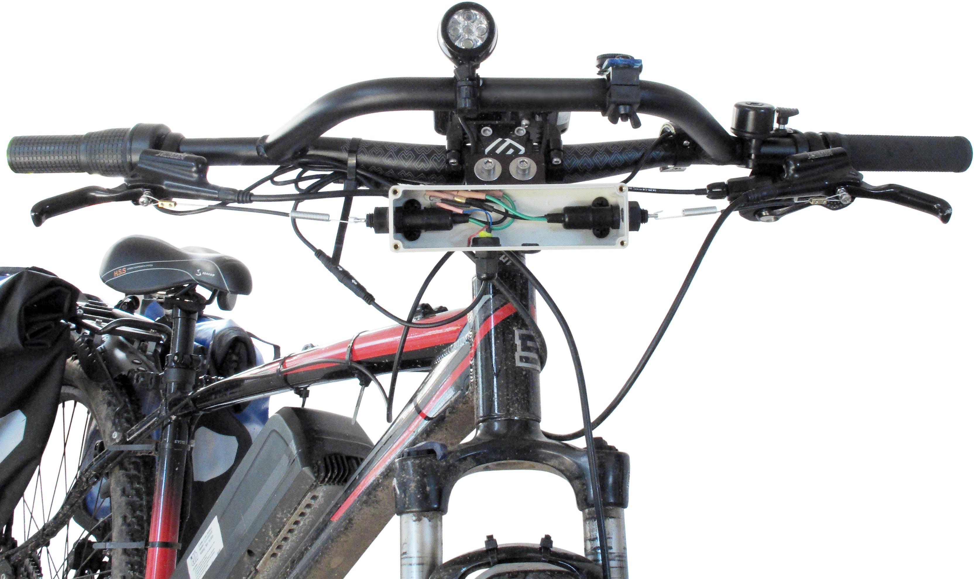
This work took place at a time when I had already ridden for many miles without kill switches. This meant that I was unaware of how much benefit they might give in practice; and while I definitely wanted them, my principal interest was in upgrading the e-bike electrics to be like that of a conventional motorbike. It had therefore been my intention to add a waterproof ABS box of 160 × 45 × 56 mm beneath the handlebars, orientated so as to allow the mounting of traffic indicators compliant with the statutory minimum separation of 240 mm. I mounted the box on an aluminium bracket attached to the handlebar stem by means of extended clamp bolts and spacers. I also put a 30° bend in the bracket, to make the front of the box vertical relative to the road. It was while doing this work that I realised that by positioning the indicator stems to be as far forward as possible, there was enough room behind them to allow the fitting of universal motorcycle rear brake-light switches (manufactured by Honnoh but available via ebay etc.). These are simple spring-loaded mechanical pull-switches, mounted by means of an M12 plastic nut, and supplied with a pull-spring that can be bent to fit a wide variety of bikes.
I must confess that, had I come up with this solution in the absence of any intention to fit indicators, it would have seemed complicated and inelegant and I would probably not have implemented it. With the indicator box present however, it became immediately straightforward, robust and cheap. The arrangement is shown below, with the lid of the box removed to show the switches inside. This, incidentally, is the original test configuration, with the switches in parallel connected directly to one of the Bafang kill-switch ports (the brake light circuit has yet to fitted). The motor cutoff function is activated by shorting the blue and black wires in the Higo Mini B3 cable (which was taken from one of the Bafang-supplied brake switches). The red wire (Hall sensor B+ 5V) is not used, but must be insulated.
click on an image to expand it in a new browser window
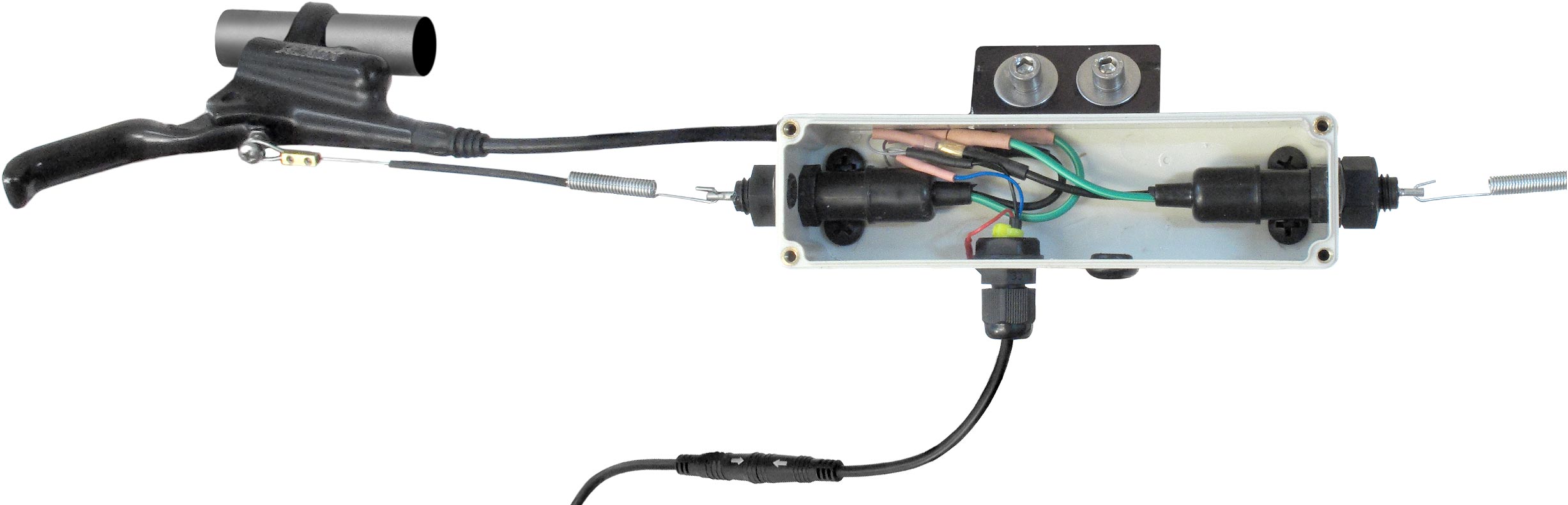
The supplied pull-springs are simply bent around the extended reach adjustment screws on the brake levers and adjusted until the switch is slightly pulled-out (but not yet closed) with the lever at rest. Motor cutoff then occurs before the brake pads are engaged. The ends of the springs are formed into loops using brass inserts taken from a small electrical connecting block. This ensures that there are no sharp wire-ends for fingers to find accidentally in the dark. The original M3 zinc-plated steel grubs screws of the connector block have been replaced with stainless A4 Allen-socket screws to prevent corrosion. The loops formed are just large enough to permit the springs to be removed without using tools.
I first tested the arrangement using a bike stand, and noted that while the shut-off of motor power was immediate on pulling a brake lever, there was a delay of about 1 second before power was restored after the lever was released. I wondered if this might noticeably reduce bike acceleration after braking, but the effect was not apparent while cycling on ordinary roads. The reason for that is probably that I did the workshop test while holding the throttle open, whereas the throttle is allowed to spring-back during normal braking. Hence there is always a delay in getting going again in practical situations, and the electronic delay is naturally obscured.
What was really noticeable about the implementation of the motor-kill function however, was the effect on braking in response to the actions of other road users. Without kill switches, there is always a heart-in-mouth moment when suddenly required to brake while travelling at speed. This, of course, is because the brakes are inefficient until the motor output ceases. You can get-used to this, and after a while might not even be consciously aware of it; but it is very noticeable when the transient sensation of impending disaster is taken away. There is also a general improvement in the responsiveness of the braking system, and this gives a greatly increased feeling of confidence in riding the bike. I quickly came to regard kill switches as essential when using public roads, and I realise that I might have avoided considerable stress had I fitted them from the outset.
I am however not convinced of the benefit of kill switches when riding off road. In that case, the speed is anyway very low, and the brakes can be used to give a subtle modulation of the motor output that cannot be achieved otherwise. The motor controller requires information from the back wheel Hall sensor in order calculate the rider's power requirement, and this necessarily involves a delay of up to one full wheel rotation ( ≤ 2.3 m with 29" wheels). The throttle also has only about 4 power levels, and so its action is too crude to allow it to be used to compensate. Controlling the motor by loading it with the brake until the system catches-up provides the solution, but not if pulling the lever causes the motor to shut down for a whole second. In my first foray onto a rough surface, I lost balance and nearly fell-off at about 2 mph because of this; and I would say that the off-road capability was badly compromised. The short term solution, of course, is to unplug the motor-kill connector; but ultimately the system used on a mountain bike needs an easily accessible switch and a warning light (the latter to remind the rider to restore the kill function when going back onto the public roads).
Lighting and ancillary systems.
In view of the preceding discussions in this and the parent article, the following circuit was devised (click on the image to enlarge it in a new tab).
The circuit includes the following features:
 Battery Isolator switch:
It was mentioned in the e-bike battery article that
plugging-in
the charger has the effect of switching the battery output back on.
This is unnacceptable, and the solution is to provide a 100A switch on
the power control box. The actual current requirement is more like 10A,
but a vehicle-battery fire-safety switch can give a good low-resistance
connection for the motor.
Battery Isolator switch:
It was mentioned in the e-bike battery article that
plugging-in
the charger has the effect of switching the battery output back on.
This is unnacceptable, and the solution is to provide a 100A switch on
the power control box. The actual current requirement is more like 10A,
but a vehicle-battery fire-safety switch can give a good low-resistance
connection for the motor.Note that the motor gets an unlimited connection to the battery, but all of the other circuits are protected by fuses. These are standard automotive fuses, except for the one in the input to the 12V switch-mode converter, which was provided as a component on the circuit board.
| An issue that arose regarding the isolator switch is that, although the contacts were made from good quality copper, the supplied nuts on the connecting studs were found to be passivated steel, with a yellowish colour that might have given the casual observer the impression that they were brass. A test with a magnet confirmed their true composition. The problem here is that any connecting lug is trapped between the nuts, and does not make direct connection to the high conductivity stud. Hence, with the original nuts done up tightly, the overall on-resistance of the switch was found to be about 0.1 Ω, which would have caused a voltage drop of about 0.8 V with the motor is at full output (max. current of around 8 A). Most of this loss can be avoided by replacing the nuts with copper or brass items (both M6 and 0BA nuts will fit on the type of switch shown). Any shakeproof or spring washers used should, of course, also be brass or copper. | 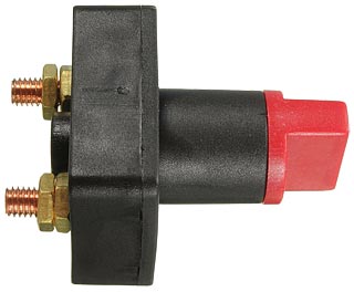 |
 50V analog meter
(on the rider's control console): By carefully dismantling an
analog voltmeter, it is possible to add a third terminal that bypasses
the series resistor.
A 2200μF 6.3V electrolytic capacitor can then be
placed
directly accross the coil. This damps the movement to give a
settling time of a little more than 1s, which prevents the delicate
device from being destroyed by shocks and vibration.
50V analog meter
(on the rider's control console): By carefully dismantling an
analog voltmeter, it is possible to add a third terminal that bypasses
the series resistor.
A 2200μF 6.3V electrolytic capacitor can then be
placed
directly accross the coil. This damps the movement to give a
settling time of a little more than 1s, which prevents the delicate
device from being destroyed by shocks and vibration.The actual battery voltage is vastly more informative than the battery status-bar, since it can also indicate switch and connector problems (this might prove important if still using the supplied mounting-plate connector). For a battery constructed by connecting 10-cell Li-ion (graphite anode) stacks in parallel, the relationship between charge status and voltage is, to a good approximation, as follows:
| % Charge | 100 | 80 | 60 | 40 | 20 |
| Voltage | 39 | 38 | 37 | 36 | 35 |
 Note that compasses and
analog
meter movements need to be kept well apart. Even using an Alpkit hoop handlebar, the
required separation is not easy to achieve. Ammeter (on the
console): A 3.75 milli Ω shunt is placed in series with the
motor feed inside the PCU box. A 20A fsd ammeter (i.e., a 75mV fsd
analog meter calibrated 0-20A) is connected across this shunt and mounted on
the console. A small switch on the PCU box gives the choice of reading
the total battery current ('All') or the current drawn by the motor on its own.
Note that compasses and
analog
meter movements need to be kept well apart. Even using an Alpkit hoop handlebar, the
required separation is not easy to achieve. Ammeter (on the
console): A 3.75 milli Ω shunt is placed in series with the
motor feed inside the PCU box. A 20A fsd ammeter (i.e., a 75mV fsd
analog meter calibrated 0-20A) is connected across this shunt and mounted on
the console. A small switch on the PCU box gives the choice of reading
the total battery current ('All') or the current drawn by the motor on its own.Note that a galvanometer with a 3.75mΩ resistor across it is naturally damped by this near short-circuit.
 12V switch-mode DC-DC converter.
A 10A output down converter permits the use of motorcycle indicators and flasher unit, a car or truck day-running light (DRL or 'side light'), and it allows the provision of a cigar socket. Note that the bike battery pack already has a USB connector for cellphone charging, but car accessories of current consumption up to the fuse rating can use the 12V socket. All of the bike lights and indicators are LEDs, and this requires a special LED (low current) flasher.
The 12V converter used by the author came in an aluminium box, which was intended to act as a heat sink for the power transistors. It is a simple matter to open the box and remove the circuit board. The transistors can then be mounted on the back of a finned heat sink (white thermal grease required), with the fins open to the air on the outside of the power control box. A little architectural silicone between the heat sink and the power box will keep the rain out.
Brake lights and Kill Switch.
The brake switches activate a TIP127 PNP Darlington transistor. This already has an on-chip resistor between base and emitter and, with an hfe of about 1000, all it takes is a single resistor and about 1mA of base current to turn it hard on. The collector is connected directly to the stop light.
Switches allow the motor cutoff function to be disabled during off-road use, in which case a red panel LED will light every time the corresponding brake is operated. This warns the rider to restore the kill function once back on public roads.
The tail-light was bought from a Chinese supplier via ebay and is branded Wuxing, type WD101. It is designed for e-bikes and scooters using 36V batteries. It has a total of 7 high-brightness LEDs, connected as one string of 4 and one of 3, with series resistors to limit the current. The stop light should always be brighter than the tail light, and so the string of 4 LEDs is the stop light. The addition of a 1N4004 diode enables the tail light to supplement the brightness of the stop light in the event that the tail light is not already in use.
One issue I found with the tail light unit was that it was built using white LEDs. This meant that the red colour, as seen through the clear-red outer cover, was not as highly saturated as it should have been. This, incidentally, is an issue that can only get worse with age, as the sun bleaches the filter. The solution was to replace all of the LEDs with red high-brightness types.
Side-stand safety. A switch on the stand uses the brake-switch kill function to disable the motor when the leg is down and the power is on, and a flashing red warning LED signals this condition. Flashing of the LED is accomplished by using the turn-indicator unit. A current of anything more that about 4mA is sufficient to operate a flasher unit intended for LED indicators.
Adapting a side-stand to incorporate a safety switch was an engineering project in its own right (see side stand article), but well worth the effort. Failure to retract the stand is immediately obvious when pulling away, particularly if a twist & go throttle is used during initial acceleration.
Note that for modern motorcycles, engine cutoff is activated when the side stand is down. So far (July 2020) no manufacturer has seen fit to produce a retro-fit pedal bike side-stand with a switch to plug into an e-bike wiring harness. This situation needs to be rectified.
 Main Lights.
Illumination of the road ahead is provided by two 6-LED ultra-high brightness units intended for use as motorcycle headlights or fog lights. These are unbranded, rated for operation from 9 to 85V, and are again bought from a Chinese supplier. They each have a built-in switch-mode power converter, which means that the current goes down as the voltage goes up. The nominal power rating of each lamp is 10W, giving a nominal current of 278mA at 36V. The luminous output of a high brightness LED can be up to 9 times that of a tungsten lamp of the same power, and these are easily in the upper range of that statistic. The two lights are both the same, the difference between dip and full being in the adjustment of the handlebar clamp in each case. Note that a switch on the console, 'cont dip' (i.e., continuous), allows the dipped beam to remain on when full-beam is selected. The ability to turn-off this latter feature allows battery charge to be conserved when necessary.
A motorcycle handlebar switch provides indicator and main-beam selection, but also has a horn button. In the UK however, most pedestrians and motorists find the use of an electric horn offensive, and that will be especially true if the person making the noise is a pedal cyclist. A bicycle should preferably have an amusingly old-fashioned audible-warning device, such as a mechanical bell or a rubber-bulb horn. This makes the horn button redundant, but a couple of diodes turns it into a headlamp flasher. A slight operational inconsistency lies in the fact that the tail-light will also flash if 'cont dip' is selected in the daytime, but the inclusion of an extra diode to prevent that does not seem worthwhile. Also, we can take a leaf out of the computer program-developer's book by saying that 'this is not a bug, it's a feature'.
One additional safety lighting feature is the provision of a day-running light (DRL). Such lights are a particularly good idea in winter or when the weather is overcast. I bought a set of 4 of these, unbranded Chinese 2-LED units with DOT compliance, rated for 10 to 30V operation. Checking on a bench PSU showed that current limiting is via a resistor. The maximum voltage of 30V is not enough for the 36V supply (it is intended for 24V trucks), and so the single unit used is fed from the 12V supply. The current drawn with an input of 12.6V was measured at 58mA, giving a power consumption of 0.73W. One bad feature of these lights is that the positive wire is black and the negative wire is white, so I marked them with red and blue H20 Hellerman sleeves to avoid confusion. On one occasion of accidentally connecting one backwards to a PSU however, it didn't work but it was undanaged.
Current practice with new motorcycles is for the lights to be on all of the time while riding. This is not a legal requirement for e-bikes however, and it will reduce the range. The low-power DRL facility allows lights to be used without significant range reduction; but the first line of defence must always be to wear high-viz clothing.
Turn indicators.The front turn-indicators are mounted on an O-ring sealed ABS box in front of the handlebar mounting point. The box external dimensions are 160 × 45 mm, and the depth is 55 mm. The width is just sufficient to place the centres of the indicator lenses 240 mm apart, which is reasonably compliant with UK minimum indicator separation regulations for motorcycles.This box also contains the brake-light switches and has a DRL unit on its front. A 6-core cable is required to connect the front box to the rider's console, with IP68 cable glands at each end to keep-out the water.
The rear turn-indicators are mounted on the same type of box as the front ones, and this is attached to the tail-light mounting plate on a luggage rack. Rear indicators only need to be ≥180 mm apart to comply with the UK motorcycle regulations, and this allows the use of smaller lamp units. The rear box also carries the tail-light unit, and is connected to the console via a 5-core cable and two IP68 glands.
There are, incidentally, retro-fit indicator kits intended for updating classic motorbikes. One such kit puts the indicator LEDs on straps that can go around the fork legs or on either side of the headlight. The problem here is that the centres of the indicators might not then be 240mm apart, in which case the arrangement will be illegal (although the garage carrying out the MOT (Government roadworthiness) inspection might not know that). For those who do not want to delve too deeply into the bike electrical system, a supply for the flasher relay can simply be obtained from the DRL feed.
 Rider's Console.
The console is an O-ring sealed box mounted on the handlebars. It has a transparent front so that the ammeter and voltmeter can be mounted on a panel inside, with white LEDs to illuminate the dials in the dark. The toggle switches are also secured on an internal panel by means of thin nuts, but protrude through the clear front and have a waterproof rubber boot over the toggle. The switch convention is 'up for on' (in keeping with military and engineering safe-working practice).
Switches:
 Main lights, front
and rear. Continuous dip.
Enables dipped beam to stay on when full beam is selected. DRL
(day-running lights), front and rear. No cutoff, front
(motor can
still be used when the front brake is applied). No cutoff, rear
(rear brake can be used for speed control on loose or wet surfaces)
Main lights, front
and rear. Continuous dip.
Enables dipped beam to stay on when full beam is selected. DRL
(day-running lights), front and rear. No cutoff, front
(motor can
still be used when the front brake is applied). No cutoff, rear
(rear brake can be used for speed control on loose or wet surfaces)LED indicators:
Full beam. Indicator reminder. Side stand down.
Flashes when the stand leg is down and power is on. Drive
motor is disabled. No front cutoff
(lights-up
when F brake lever is pulled). No rear cutoff
(lights-up
when
R brake lever is pulled).Indicator LEDs are 6V bezel types, also mounted on the panel inside the waterproof box. They are provided with extra padding resistance to establish a running current of about 10 mA.
 Cables leading to the console from the power control unit (PCU), the
tail unit, and the front indicator unit all have in-line
plug-and-socket IP68
connectors. This allows the modules to be separated for service. The
handlebar switch (Indicators, Main / Dip, Flash) does not need such a connector because it can be split
and removed from the handlebar by removing two screws.
Cables leading to the console from the power control unit (PCU), the
tail unit, and the front indicator unit all have in-line
plug-and-socket IP68
connectors. This allows the modules to be separated for service. The
handlebar switch (Indicators, Main / Dip, Flash) does not need such a connector because it can be split
and removed from the handlebar by removing two screws.TBC . . . . .
Engineering data:
UK Road Vehicles Lighting Regulations 1989. 1796 schedule 7. Original (as made), unrevised. For motorcycles:
Dist. between front indicators is 240 mm or greater.
Dist. between rear indicators is 180 mm or greater.
Regs are not clear on how this distance is to be measured - it probably meant 'bulb to bulb' in 1989. At least 240 mm between middles of front indicatior lenses should therefore be OK (also, ≤ 250 W e-bikes don't have to pass the MOT test, but compliance is advisable).
Higo Mini-B series connectors. IP66 in-line with 1 m cable attached. Panel mount versions also available.
Honnoh Brake Light switch: The switch can be secured by means of an M12×1.75 nut, but the thread actually appears to be a special 7/16" × 15tpi (11.1 × 1.7mm) size. This is not a standard UNC thread.
 Regenerative braking
E-bikes do not have regenerative braking. One reason for that is that a mid-drive pedal-assist motor cannot be used as a generator in a freewheel system. In order to work as energy recovery devices, any motors must be constantly locked to the wheel rotation while the bike is in motion. Best 2-wheel transportation practice also dictates that the drive torque should be applied to the rear wheel, while most of the braking torque should be applied at the front wheel. Taking these issues into consideration leads to the conclusion that a generator large enough to provide a significant braking effect is best fitted to the front wheel. This generator, furthermore, should have very low drag when not loaded. The type of generator that fits the bill is, of course, a large direct drive (gearless) brushless hub motor. Such motors are admittedly, somewhat heavy (2.6 to 7 kg), but they are available.
A major problem with fitting a large front hub motor, in addition to the normal 250 W mid-drive system, would lie in convincing the authorities that the regenerative braking system cannot be used to power the bike. Indeed, if the bike is also capable of off-road use, it would be ridiculous not to use the front motor to obtain a 2-wheel drive system. The inevitable custom electronic system would then, unfortunately, present a formidable, possibly insurmountable, challenge in the matter of obtaining Vehicle Approval.
|
E-bike conversion |
E-bike Legal |
E-bike battery |
E-bike electrics |
Side stand |
Steering damper |
Electric m/c |