Correction
images for lens radial distortion & chromatic aberration using
software
By David Knight
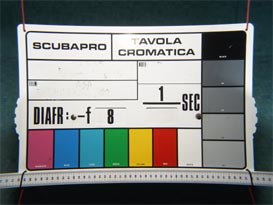
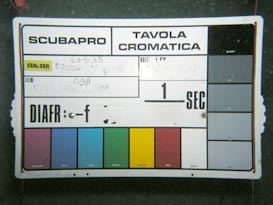
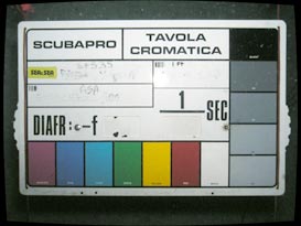
Geometry before |
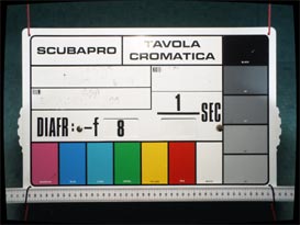
Geometry after |
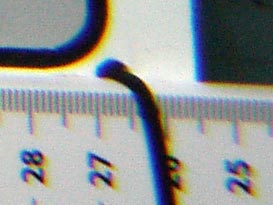
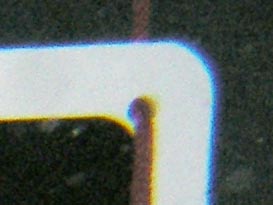
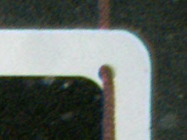
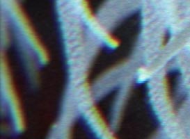
Corner detail before |
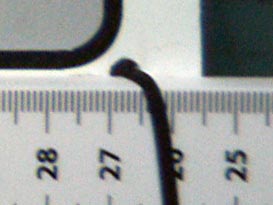
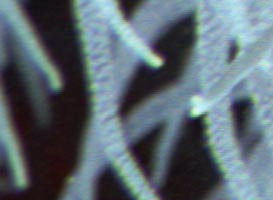
Corner detail after |
Whenever a lens designed for use in air is used underwater, some degree
of image distortion is inevitable due to the water-air boundary (which
is, in effect, a crude lens). If the boundary is flat, there will be
pincusion distortion, the severity of which increases with the angle of
coverage. This distortion (being classed as a type of 'radial
distortion') occurs because the image magnification increases with
distance from the centre of the picture.
In addition to the
obvious large-scale effect, the boundary has the property that the
resulting image magnification (and to some extent, the degree of radial
distortion) is a function of wavelength. This means that the
magnification will be different in the red green and blue colour
channels. The result will be colour fringing in off-centre detail,
otherwise known as 'chromatic aberration'.
If a lens is
perfectly rectilinear in air, i.e., it has been designed to preseve
straight lines and right angles in the picture; its rectilinearity can
be maintained underwater by mounting it behind a dome port and placing
the entrance pupil at the centre of curvature of the dome. In practice
however, the placement of the entrance pupil is unlikely to be exact;
because dome port extensions are only manufactured in fixed lengths and
the entrance pupil may be difficult to locate. Moreover, if a zoom lens
is used, the entrance pupil position will change with focal length. If
the entrance pupil is too close to the port, some pincushion distortion
will be introduced; and if too far away, the converse effect, 'barrel
distortion' will occur. Furthermore, although the dome port can give
some measure of geometric compensation overall, it will still introduce
a small amount of chromatic aberration.
Notwithstanding the
effect of ports, the camera lens itself may be far from perfect. This
is particularly the case with zoom lenses of the type which offer a
wide focal length variation range. Such lenses are usually only
rectilinear at one particular focal length setting (if at all), and the
overall geometry is sometimes actually improved when the lens is used
with an underwater port.
The unwitting
introduction of chromatic aberration is highly undesirable because it
degrades image quality. The uncontrollability of image geometry is also
annoying in general, and deleterious to the scientific and technical
applications of photography. With the advent of digital photography
however, these privations are completely avoidable by the use of
software radial-correction techniques.
Various image editing
programs now offer radial correction facilities. Most of the
image adjustments demonstrated below were carried out using the 3
rd
party Photoshop plugin 'Panaroma Tools'; which permits very accurate
image correction but is complicated to use. Also discussed later is
Adobe Photoshop Lightroom, which is considerably cheaper than the full
Adobe Photoshop program, has a lens correction facility with simple
slider controls, and is suitable for dealing with all but the most
inadvisable of lens and port combinations.
Panorama Tools
'Panorama Tools' (or 'PanoTools' for short), is a set of software
utilities written by Prof. Helmut Dersch and released under the GNU
Public Licence (GPL). These programs were primarily designed to aid in
the construction of panoramas from multiple photographs, but provide
numerous general-purpose image processing functions. The functionality
of relevance to this discussion lies in a module called 'correct',
which provides a radial-shift facility for the removal of barrel and
pincushion distortion. 'Correct' also works on red, green, and blue
channels independently, and so can remove chromatic aberration. This
means that even a far-from-ideal optical arrangement such as a lens
with a field of view (FOV) of 97° (35mm equivalent focal length
= 19mm) placed behind a flat port can be made to perform as a fully
water-corrected lens. The correction determined for a particular lens +
port combination and zoom setting moreover can usually be applied to
all photographs so produced (focusing and aperture changes do not
significantly alter the reguired corrections) and so after an initial
experimentation phase the correction process is reasonably quick and
easy. Thus the physical measures which might be taken to preserve image
rectilinearity are no-longer strictly necessary (although dome-ports
have other advantages as we will see).
PanoTools is available for various
operating systems and can be used on its own or as a set of plugins for
popular image-editing packages. To find out more, read the articles at
wiki.panotools.org
and
panotools.sourceforge.net.
For a 16-bit PanoTools installer for Windows, including automatic
installation of Photoshop plugins, see the website of Jim Watters:
photocreations.ca/panotools.
The discussion to follow refers to the use of PanoTools with Adobe
Photoshop on a Windows platform.
Image Files
Best results will be obtained by working with image files which have 48
bit-per-pixel (bpp) colour depth, i.e., converted RAW files saved as 16
bit-per-channel RGB TIFF or PSD files. If the camera will only output
JPEG files, use the highest available output resolution and quality
settings and convert to TIFF or PSD for intermediate adjustment.
Be careful not to
save adjusted versions over the original file, always use 'Save As...'
and change the filename. There is a quality loss on applying JPEG
compression, so only save as JPEG as the final step in working on an
image. The GIF format is unsuitable for high quality photographs, due
to restricted colour depth.
The required correction for a
particular image is largely dictated by the focal length of the lens
used. It is therefore useful to have some means for reading EXIF data
(i.e., the camera settings information embedded in the image file).
Most RAW file conversion utilities provide this.
Video Monitor
Performance
You will not be able to evaluate your corrections properly if your
video monitor suffers from geometric distortion or poor colour
convergence (i.e., inaccurate superimposition of the red, green, and
blue pictures). Since such issues relate only to CRT type monitors, it
is recommended that corrections are performed only with the aid of a
modern flat panel display.
Using
Radial
Shift
 You
should only apply radial shift correction to uncropped images. The
point is that the correction causes the image to expand or contract
about its centre point, and if you crop the image, the centre will no
longer correspond exactly to the lens axis. Therefore apply radial
correction first, crop the image later. You
should only apply radial shift correction to uncropped images. The
point is that the correction causes the image to expand or contract
about its centre point, and if you crop the image, the centre will no
longer correspond exactly to the lens axis. Therefore apply radial
correction first, crop the image later.
Images must be in RGB mode (not CMYK). Assuming that you have loaded an
image that requires correction, when you select the 'Filter / Panorama
Tools / Correct' menu item you will see an applet box like
this: → |
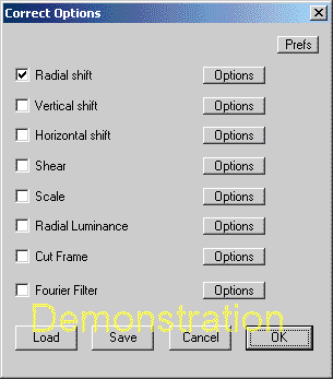 |
Select 'Radial shift' (tick the box as per the illustration), and click
the Options button. The applet shown below will then appear.
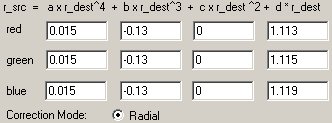
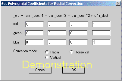 |
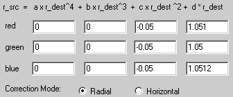
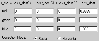
This box invites you to
enter polynomial coefficients
for the correction, and the initial values presented when you first use
the tool are those those do nothing at all to the image. You don't need
to understand the maths to use the tool, but a knowledge of what each
of the coefficients does will ensure that you adjust them in a sensible
way. |
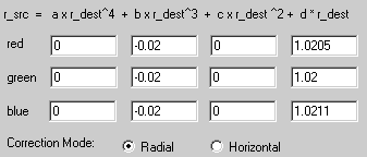
The coefficients, from left to right are known as a, b, c, and d. d is
the first-order correction coefficient, c is the second-order
coefficient, b is the third-order coefficient, and a is the
fourth-order coefficient (the 'order' is the power to which the
quantity r
dest is raised).
The first-order coefficient d changes only the size of the image
without affecting the geometry. By expanding or contracting the red,
green, and blue images independently about the lens axis you can
perform a first-order correction for chromatic aberration. This is
usually all you need.
By changing the values of the higher-order coefficients, you can cause
the image to expand or contract about its centre by an amount that
depends on the distance from the centre to the pixel in question.
Changing second and higher order coefficients therefore allows you to
correct for barrel or pincushion distortion.
Making the sum of the coefficients a+b+c+d=1 conserves the original
image height at the centre. Making the sum greater than 1 reduces the
height of the image, and making the sum less than 1 increases the
height of the image.
To correct for pincushion distortion, start by using positive values
for the third-order (b) coefficients. To correct for barrel distortion,
use negative values.
Interpolation
Quality
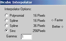
If you click the 'Prefs' button of the Correct Options applet, and then
click 'More', you will be given the various interpolator options shown
right. Use polynomial interpolation for speed when determining
correction coefficients, and use sinc interpolation for maximum quality
when applying the correction finally. |
 |
Adjustment
Strategy
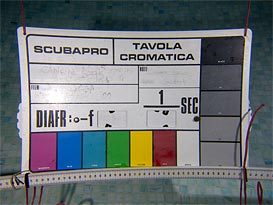
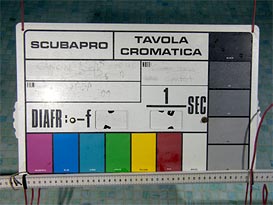
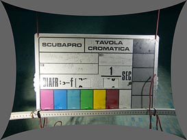
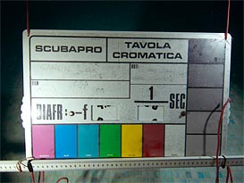
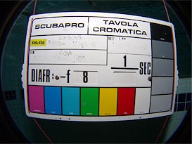
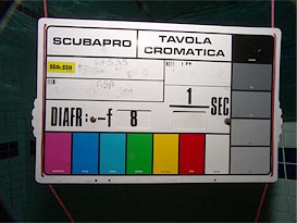
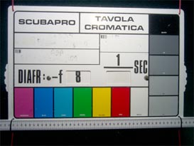
Ideally, you should take a photograph of a rectangular test-card with
white-on-black detail in at least one of the corners.
Start by correcting only the image
geometry, i.e., use the same coefficient values for the red, green, and
blue channels. Simple barrel or pincushion distortion is an aberration
that depends on the cube of the distance from the image centre, and so
it is best to start by adjusting the 'b' (third order) coefficient. If
the image has barrel distortion, try b= -0.1 and adjust 'd' so that the
sum of coefficients is 1, i.e., d=1.1. If the image has pincushion
distortion, try b=0.1 (and hence d=0.9). Look at the result and see if
more or less correction is needed and adjust 'b' and 'd' accordingly.
Hold down the [control] key and hit the Z key to revert to the original
image before applying a new correction. To retain maximum image
quality, the correction should always be carried out in a single
operation, not incrementally.
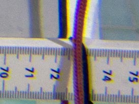
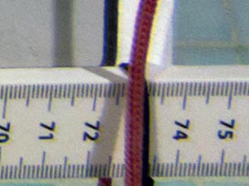
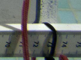
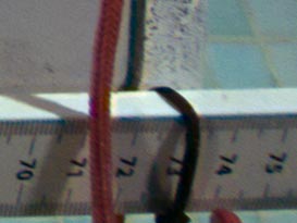
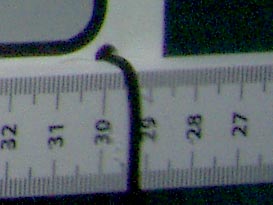
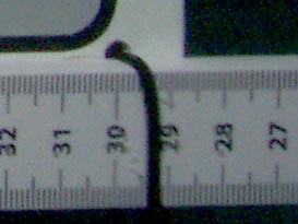
You can assess the straightness of
straight lines by laying a clear plastic ruler against the monitor
screen. Photoshop guides are only useful if the lines in the picture
are exactly horizontal or vertical, which is unlikely. You can place a
diagonal line on the picture with the Marquee tool, but a ruler is
quicker. Note that it is important to use some instrumental means for
determining straightness because an optical illusion occurs on
comparing a distorted and an undistorted image, such that the corrected
image may sometimes appear to be distorted in the opposite manner to
the original. Adjust the coefficients until straight lines are on
average straight. If a line appears to undulate after a third-order
correction, then some second or fourth-order correction may be needed.
Hence increase the magnitude of 'a' or 'c' while decreasing the
magnitude of 'b' by a similar amount, and so-on until you have geometry
as near perfect as you can be bothered to obtain. In general, even the
most appalling lens-port combinations will succumb to a correction
involving both 'b' and 'a' or 'c', and it is rarely necessary to use
non-zero values for all three.
With your geometrical correction
parameters now determined, you can apply a first-order correction for
chromatic aberration. For this, the green channel, being the middle
colour in terms of wavelength, should be treated as the reference
channel (i.e, the green channel is assumed to be correct and the others
are brought into convergence with it). Hence adjust only the 'd'
coefficients of the red and blue channels, leave green alone.
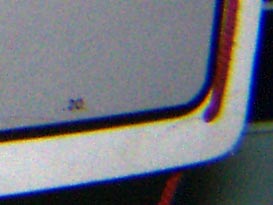
Having reverted to the uncorrected
image ( [ctrl] Z ), look for a white-on-black detail near one of the
corners of the picture, magnify it, and and note any lack of
convergence of the red, green, and blue images. If you are just
correcting for the effect of an air-water boundary (i.e., assuming that
the camera lens does not make a major contribution to the aberration)
you will find that the blue image is slightly too large, and the red
image is slightly too small. If this is the case, then increase the 'd'
coefficient for blue slightly, and reduce the 'd' coefficient for red.
Note also that, for water, the difference in refractive index for green
and blue light is about twice the difference for green and red, and the
deviation observed is roughly proportional to this difference. Hence,
presuming that you are correcting mainly for the underwater port, you
will probably need to apply about twice as much correction to the blue
channel as to the red channel. Start by increasing the blue 'd'
coefficient by 0.003 and reducing the red 'd' coefficient by 0.0015.
Fiddle with the parameters until you have exact convergence in your
chosen corner feature. Toggle between the corrected and uncorrected
versions of the image by hitting [ctrl] Z repeatedly. Notice that when
convergence is obtained, there may be a slight blue haze around the
feature: this is because lenses in general focus short-wavelength
(blue-violet) light slightly less sharply than they focus red or green
light (but the effect also depends on the filtration system used to
separate red, green, and blue light in the camera). Once you have a
first-order correction, inspect the image all over to see if chromatic
aberration has reappeared in some regions. If it has you will need to
make a second or higher-order correction, i.e., you will need to make
tiny adjustments to the blue and red 'c' coefficients and so on; but
such corrections are time consuming and rarely lead to noticeable
practical improvement.
Always apply any correction you make to
the completely uncorrected image, i.e., hit [control] Z after every
trial. PanoTools stores your last attempt in a preferences file, and
gives it to you as a starting point for the next go. Hence you will
quickly home in on a set of coefficients which performs both geometric
and chromatic corrections in a single operation; and this formula will
usually work for all subsequent photographs taken using the same lens,
port, and zoom-setting combination. Use the 'Save' and 'Load' buttons
at the bottom of the 'Correct Options' dialogue box to store and
retrieve previously determined coefficients.
Tip (Windows OS): If you hold down the [Alt] key and hit the [PrtSc]
key when the correction coefficients dialogue box is on the screen, it
will be saved to the clipboard. You can then create a new file (File /
New) and paste the clipboard into it (Edit / Paste), then save this
file with the images concerned. This is useful if you want to create
documents explaining what you have done (and is the method used to show
dialogue boxes here). Also, after a few years, sereral new computers,
and various software upgrades; you might lose your preset data, in
which case the applet box snapshot will come in useful if you want to
work-up more images from the set.
Examples
 |
27
mm
lens and flat port
Olympus C-5060 camera (5.1 Mp 1/1.8" RAW) in PT-020 housing with PPO-01
standard port.
 Zoom setting = maximum wide (35
mm equiv: 27 mm). Zoom setting = maximum wide (35
mm equiv: 27 mm).
 Coverage: 77° in air,
56° underwater. Coverage: 77° in air,
56° underwater. |
 Pincushion
distortion before Pincushion
distortion before |
Geometry after |
Chromatic aberration before |
Residual aberration after |
| Radial
correction
coefficients: |
 |
To show the extent to which the optical effects demonstrated above are
due to the water-air boundary, a photograph was taken of the test-card
in air, using the bare C-5060 camera (no port) and the same zoom
setting (max wide).
Geometry before correction. |
Geometry after correction. |
 Chromatic
aberration before
correction. Chromatic
aberration before
correction. |

Chromatic aberration after correction. |
| Radial
correction coefficients: |
 |
In this case, note that the lens on its own produces some barrel
(fisheye) distortion at the widest setting, and so actually compensates
for the distortion introduced by the water-air boundary when the camera
is used underwater. The chromatic aberration is also minor, and quite
different from that caused by an underwater port. Here we find that a
white object has a magenta fringe on the outside, and a green fringe on
the inside. The outer magenta fringe means that both the red and the
blue images are too large. The inner green fringe means that the green
image is too small, which is the same as saying that the red and blue
images are too large, i.e., the inner green fringe is simply the colour
complement of the outer magenta fringe. The upshot is that a small
compensation can be achieved, in this case, by slightly reducing the
sizes of both the blue and the red images.

You
will, of course, see different
colour fringes with other lenses, and the fringe colours will change
while you are working towards an optimum correction. Consequently, to
work out the required direction of adjustment, you may find it helpful
to memorise the complementary colours. These are as follows:
| Secondary
Colour |
Complementary
Colour |
| Cyan = Green + Blue |
Red |
| Magenta = Red + Blue |
Green |
| Yellow = Red + Green |
Blue |
The wedge-shape of the test-card in the final image above,
incidentally, is simply due to the fact that the camera was not
pointing directly at the card, i.e., it is an effect of perspective not
lens distortion (you can pull-out this effect using the Photoshop
Free-Transform tool). A slightly oblique camera angle does not affect
the usefulness of a test shot because determining a geometric
correction is merely a matter of making straight lines come out
straight
 |
Epoque
DCL-20 wide converter and 27mm lens
Epoque DCL-20 0.56x wide-angle converter attached to Olympus C-5060
camera in PT-020 housing with standard port . Zoom setting = maximum
wide. |
Barrel distortion before |
Geometry after |
Chromatic aberration before |
Residual aberration after |
| Radial
correction
coefficients: |
 |
Note that the unprocessed image has a circular vignette, and that the
correction process reduces its effect so that only a small amount of
final cropping will be required. The vignette is due to the fact that
the maximum angle of coverage of the camera lens exceeds that for which
the DCL-20 conversion lens was designed.
 |
19mm
lens and flat port
Olympus C-5060 camera with WCON-07C 0.7x wide-angle converter in PT-020
housing with PPO-02 flat wide-port. Zoom setting = maximum wide,
Coverage: 97° in air (35mm equiv: 19mm), 68° underwater. |
Pincushion distortion before |
Geometry after |

Chromatic aberration before |
Residual aberration after. |
| Radial
correction
coefficients: |
 |
Under normal circumstances, the use of a 19mm equivalent lens behind a
flat port is something no serious underwater photographer would
consider. The PPO-02 packaging even had warnings about lens-distortion
printed on it, and true to the laws of optics it gives chromatic
aberration so bad that it can even be seen in the de-magnified image
given above (top left picture). After correction however, the results
are perfectly acceptable.
Once again, we can separate the effect of the underwater port from the
performance of the optical system overall by photographing the test
card in air using just the C-5060 camera and the WCON-07C wide
converter.
Geometry before correction. |
Geometry after correction. |

Aberration before correction. |

Aberration after correction. |
| Radial
correction
coefficients: |
 |
As with the camera on its own, the camera with the Olympus
wide-converter also produces fisheye distortion and magenta-out,
green-in, chromatic aberration. Once again, a small amount of chromatic
compensation is possible, but the initial aberration is by no means
problematic.
From the above we can see that, when used in conjunction with a
wide-angle lens, a flat port introduces pincushion distortion and
pronounced blue-out, red-in, chromatic aberration, both of which can be
corrected fairly easily using software. A camera lens that exhibits a
certain amount of barrel distortion when used in air will to some
extent offset the pincushion due to a flat port, but it will usually
have little effect on the aberration.
Limitations
of the Correction Process
One issue which must be understood from this discussion is that the
procedure outlined will turn a good air-corrected lens into a good
underwater-corrected lens, but it cannot turn a bad lens into a good
lens. The point here is that if the lens behind the port can produce
sharp pictures when used in air, then the correction process will
restore its ability to produce sharp pictures underwater; but if it
gives fuzzy pictures in air, it will also produce fuzzy underwater
pictures.
At risk of repetition, we should also
discuss the fact that the coefficients required for a particular lens
and port vary according to the zoom setting. This however, will trouble
old-school underwater photographers very little; since for pictures
other than macro, they will all automatically wind the zoom to its
widest angle and leave it there. The simplest operational policy is
therefore to make test-card shots and determine coefficients for a set
of easily repeatable focal-length settings, and stick to these settings
when taking real pictures. Alternatively, make a set of test-card shots
at reasonably closely spaced focal-length intervals and plot a graph of
the way in which the coefficients vary with focal length. You can then
use the zoom at will, and provided that you have a way to record the
zoom setting with the image data, you can interpolate the graph for
corrections at your randomly chosen focal lengths. If this sounds like
hard work, observe that it is always advisable to try out a camera
system in a swimming pool before venturing into the ocean, and a
once-and-for-all, acquisition of calibration shots will take about 10
minutes.
Unsharp
Masking
Some digital cameras (particularly, but not exclusively, inexpensive
ones) apply unsharp masking to the image by default. You should turn
this feature off if at all possible, since it will interfere with any
corrections you make for chromatic aberration and lead to an
unsatisfactory result. The effect of unsharp masking is to increase the
contrast at brightness transitions in the image (edges); sometimes with
overshoot that creates black or white fringes around objects. If you
apply a correction for chromatic aberration, these fringes will blur,
and white fringes will split into three colours. The result is a
picture that is notionally corrected, but has more colour fringing and
softer edges than before; i.e., correction becomes pointless and
reduces the subjective image quality. If you must use unsharp masking,
use it only on the final image, use it only after the image has been
re-sized to its final resolution, and never do it over a radius of more
than about 0.7 pixels. The general rules for unsharp masking are very
simple and easy to remember:
Rule #1: Don't do it.
Rule #2: If you must do it; make it the final editing operation.
Why Aperture
and Focus Settings Don't (usually) Matter
The correction procedure described above works regardless of the lens
aperture setting because, for a reasonably well designed lens, the
geometry of the image is not affected by the aperture. Likewise the
geometries of the separated R G and B images are not affected by
aperture, which is why you can't reduce the chromatic aberration of a
lens and port combination by stopping down. What the aperture does is
change the size of the circle of confusion (the extent to which a point
is reproduced as a fuzzy circle), and so while the sharpness of a
feature in the red green and blue channels may vary with aperture, its
centre-point should always land on the film or sensor in the same
place. Hence, once you have obtained exact convergence of the red green
and blue images, changing aperture may alter the amount of coloured
haze around a feature, but changing the correction will not result in
better convergence. It is of course, possible to make a lens in which
this convergence will wander, by failing to place the iris at the nodal
point, but in the days of computer-aided design, such abominations are
unlikely to be encountered.
The focus setting, incidentally, does
have an effect; but for a wide-angle lens, the difference between
closest-focus and infinity is likely to be too trivial to warrant any
adjustment of the correction coefficients. For close-focusing macro
lenes however (e.g., 1:1), particularly when the image format is
relatively large; there can be a significant change in both aberration
and geometry as the object distance is varied. For more information on
the behaviour of macro port systems, see the
flat port theory
article
Why Dome
Ports are Still a Good Idea
Although the techniques outlined here make the expense of a dome-port
system less necessary, a dome port has some very compelling advantages,
which software correction cannot hope to match. The first point is that
a flat-port increases the effective focal length of a lens, due to
refraction at the air-water boundary, and hence reduces the angle of
coverage. Since the idea in underwater photography is to use a
wide-angle lens in order to put the minimum amount of water between the
camera and the subject, a flat-port somewhat defeats this intention.
The second point is that the dome-port was introduced in the 1960s as a
way of avoiding port-vignetting with very wide-angle lenses (its
optical advantages were actually discovered by accident) and it will
obviously still fulfil this purpose. The third point is that a
flat-port introduces pincushion distortion, and radial correction
applies a compensatory barrel distortion. This means that there is
barrel-shaped vignette in the corrected picture, which will have to be
cropped-off before the picture is ready for presentation. The upshot is
that you will lose up to about 10% of the format area in correcting a
flat port, reducing the effective number of camera pixels and so
causing a small reduction in the maximum available resolution. Thus the
lens-port combination that gives the least distortion is the best
starting point for radial correction, because it maximises the usable
format area.
Dome
Port Examples
 |
19mm
lens with 6" dome port
Olympus C-5060 + WCON-07C 0.7x wide converter, in Ikelite 6130.61
housing with DP60 dome port (3" internal radius). Zoom setting = max.
wide. Angle of coverage in air and water: 97° (nominal). |
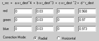
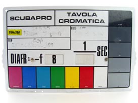
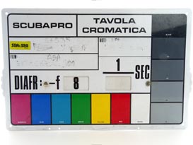
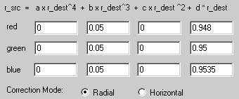
Geometry before correction |

Geometry after correction |
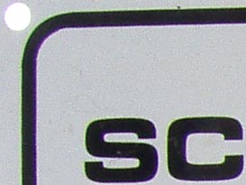
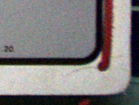
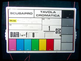
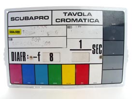
full-size detail before correction (aperture=f/8) |
full-size detail after correction |
| Radial
correction
coefficients: |
 |
Test pictures for the bare camera lens in air were given earlier, and
show that the dome port introduces no additional geometric distortion.
The barrel distortion in the uncorrected picture above is due entirely
to the zoom lens (the centre of curvature of the dome is at the
entrance pupil). The dome port does however introduce a small amount of
chromatic aberration, this being a consequence of the extremely wide
angle of coverage (97° nominal), but the result after
correction is virtually perfect in this respect. The distance from the
front of the dome to the test card was 256mm (calculated) to record a
subject field width of 610mm after correction. The camera was set in
macro focusing mode to cope with the proximity of the virtual image
produced by the curved air-water boundary. The aperture setting was f/8.
27mm lens
with 6" dome port
Olympus C-5060 camera in Ikelite 6130.61 housing with DP60 3" radius
dome port. Camera zoom setting = max wide (35mm equiv. f=27mm). Angle
of coverage: 77° in air (nominal), 73° underwater
(actual, measured).
Geometry before correction |
Geometry after correction |
full-size detail before correction (aperture=f/8) |
full-size detail after correction |
| Radial
correction
coefficients: |
 |
Although the DP60 dome port was designed for the WCON-07C, it can still
be used with the bare camera lens. In this case however, the lens
entrance pupil ends up slightly behind the centre of curvature of the
dome, and so the in air coverage of the lens (77°) is not
exactly conserved. Actual coverage underwater (measured using a method
described in the
angle
of coverage article), turned out to be
73.4±1.1° at a lens pupil to subject distance of
0.75m (but the fact that this figure is less then 77° is
actually due to expansion of the diagonal in the correction for barrel
distortion, rather than misconvergence of the entrance pupil and dome
centre). Using a dome port on its own with the camera therefore gives
wider coverage than when the camera is used with the WCON-07 and a flat
port (only 68°); and the amount of chromatic aberration
produced by the dome is effectively negligible at 73° coverage.
A dome port for wide angle photography is evidently a very good idea.
Using Radial
Correction with Film Cameras
Although this article has so-far been about radial correction of
digitally produced images, there is no reason why it cannot be applied
to images scanned from film. Operational points to note are firstly:
that the slide or negative must be scanned full-frame and cropped to
the frame border (so that the lens-axis corresponds reasonably
accurately to the centre of the picture); and secondly: any dirt specks
on the film should be removed before correction (using the Photoshop
cloning stamp or its equivalent) because they will acquire colour
fringes after correction. Also note that the correction for chromatic
aberration may not be quite so effective (it depends on the film), the
reason being due to the spectral-bandwidth (wavelength spread) of the
filters used to separate the three colour images. The filters used in
digital cameras are usually fairly sharp, giving three almost discrete
sampling wavelengths, which makes chromatic correction extremely
effective. The dye-filters used in film, on the other hand, are often
rather broad and prone to spurious responses, and the scanned RGB image
must be synthesised from a CMY image; all of which means that there
will be some dispersion within each colour channel, and hence more
coloured haze around image features after correction.
Film Examples
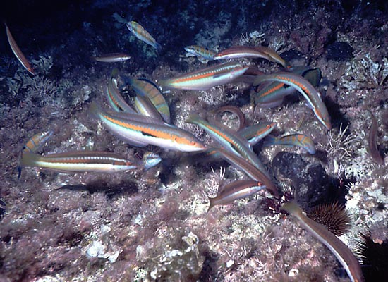
50mm Macro
lens with Flat Port
Sigma 50mm f/2.8 macro lens (~46° coverage in air) with 3/8"
thick acrylic flat port. Kodachrome 200 film. Port to subject distance
(from memory) about 0.5m.
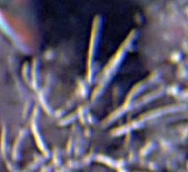
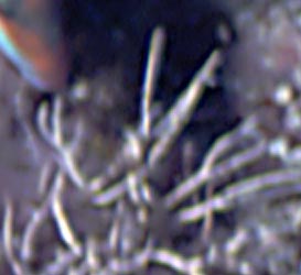
Raw scanned image, uncropped. |
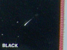
Corner detail before correction.
Corner detail after correction. |
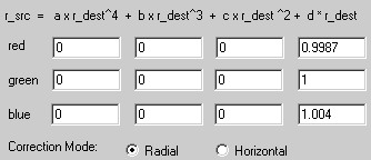
Radial
correction
coefficients
(first order only): |
 |
In this case no geometric correction was applied for the simple reason
that no test-card shots were available (and the camera system passed
out of service long ago). If you can't see distortion moreover (and you
don't need to make measurements from the photograph) there is arguably
no point in correcting for it. Chromatic aberration in the original is
not severe, as should be expected for the optical system used (the
detail images are considerably more magnified than for the previous
examples); but if you want to blow an image up to poster size, the
radial correction is evidently worthwhile.
 |
35mm
W-Nikkor Lens
Nikonos camera with W-Nikkor 35mm f/2.5 lens (air corrected underwater
lens with flat glass front element), Coverage: 62° in air,
46.5° underwater. Kodachrome 200 film. |
 Uncropped image after correction.
Edge detail before correction. |
Edge detail after correction. |
Radial
correction
coefficients
(first order only): |
 |
No geometric correction was applied for the same reason as before.
The 35mm W-Nikkor used on its own is difficult to focus and
consequently, for this author at least, produced a fair proportion of
useless pictures. The picture above is not particularly sharp, but it
is one of the better examples from the few occasions on which the
author decided to give the lens a try without its close-up attachment.
In the off-centre detail of the picture
shown above, blue light is considerably more out-of focus than green,
and green is more out of focus than red. Hence there is a blue haze
around details after correction. The coefficients for radial correction
were determined using the detail shown, but the final coefficients are
a compromise (best average) obtained by looking all over the picture.
The author was intrigued to discover that the picture 'sprang to life'
after correction: coloured patterns on the bodies of the fish suddenly
fell into register, indicating that the general fuzziness of pictures
taken with the W-Nikkor 35mm is as much due to chromatic aberration as
it is due to inaccurate focusing.
Collected
Coefficients for a Flat Port
Shown in the table below are the shifts in the first order coefficient
(d) that were used in order to correct for chromatic aberration in the
flat port underwater picture examples given above. Where correction
coefficient shifts for the lenses in air were known (27mm and 19mm)
these have been subtracted from the values for the lens and underwater
port combined.
| Shift
in d coefficient |
Angle
of Coverage of Camera Lens
(and 35mm equiv. focal length) |
97°
(19mm) |
77°
(27mm) |
62°
(~35mm) |
46°
(50mm) |
| Red |
-0.003 |
-0.0025 |
-0.0013 |
-0.0015 |
| Blue |
+0.0023 |
+0.0019 |
+0.004 |
+0.003 |
Obviously there is considerable scatter in these data, especially in
the shifts for blue light, and this can be accounted for in two ways:
Firstly there will be some deviation away from the value required for
the port alone in the cases where the coefficient shifts for the lens
in air are unavailable. Secondly, the final choice of coefficients is
always something of a compromise, and the intention was to determine
them without forcing them to agree to some predetermined scheme (and
there is considerable latitude in choosing the blue coefficient when
blue is less sharply focused than red or green). There is a trend
nonetheless, and it is consistent with a theoretical analysis given
elswhere (see
flat
port theory),
which shows that chromatic aberration caused by the water-air boundary
diminishes as the angle-of-coverage is reduced; and settles down, for
long focal-length lenses, so that the radial displacements of the red
and blue images relative to green are proportional to the differences
is the refractive index of water for red and blue light relative to
green.
To clarify a point made briefly earlier; it is useful to note that, if
the chromatic aberration seen is entirely due to an air-water boundary,
then there is every reason to expect that the coefficient shift for
blue will be about twice the shift for red, and that the shifts will be
in opposite directions. This can be understood by presuming that the
manufacturer of the sensor or film will have tried to choose primary
colours at wavelengths corresponding reasonably closely to the peak
spectral responses of the cone cells in the human eye. These peak
response wavelengths are at 560nm (red), 530nm (green), and 424nm
(blue), but most colour photography systems are based on old research
that places than at about 600 (R), 540 (G) and 450nm (B) . Data from
Kaye and Laby (ISBN 0-582-46354-8) give the refractive index for pure
water at wavelengths close to the traditional primaries as follows:
| Wavelength
/ nanometres |
Refractive
index
at 20°C |
Difference
from green |
Difference
/% |
| 435.8 |
1.340210 |
+0.005744 |
+0.430
% |
| 546.1 |
1.334466 |
0 |
0 |
| 632.8 |
1.331745 |
-0.002721 |
-0.204
% |
Since the deviation between the red, green, and blue images at a
particular point in the image is small, the relationship between
deviation and refractive index will be almost linear (i.e., directly
proportional). Hence, since the magnitude of the refractive index
difference between blue and green is about twice that between red and
green, and one is positive while the other is negative; we expect the
radial deviation to follow roughly the same pattern.
Adobe
Photoshop Lightroom
Panorama Tools allows images to be corrected to a very high degree of
precision, but the interface can hardly be described as intuitive.
Also, we can observe, that a first-order (linear magnification)
correction for chromatic aberration is usually sufficient; and most of
the required geometric correction can be accomplished by adjusting only
the third-order (cubic-law) coefficient. This means that a correction
facility very nearly as good as has been required for the
demonstrations given so far, can be provided by a software interface
with simple slider controls. One such interface is provided by Adobe
Photoshop Lightroom.
Lightroom is likely to annoy most
professional computer users with its attempts to take charge of file
management; but if you can come to terms with its workflow concepts
(importing, libraries, development and exporting - rather than simply
opening, editing and saving files) and its unhelpfulness if
the user should dare to manage files it thinks it owns using the
operating system (it becomes necessary to delete moved or re-named
files from the library and re-import them), it offers a large number of
camera RAW format converters, an EXIF reader, and some good basic image
adjustment tools. It is also aimed at the amateur user, and so is a
great deal cheaper than Photoshop.
Some examples of optical corrections
performed using Lightroom are given below.
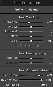
24mm lens
with flat port
Canon PowerShot S100 camera in Recsea housing. Camera zoom setting =
max. wide (35 mm equiv. f = 24 mm). Aperture = f/5.6.
Lens FOV = 84° in air, 60° underwater.
Geometry and aberration before correction:
Geometry and aberration after correction.
The lens correction
adjustments made using Lightroom
are shown on the right.
Note that in earlier work with PanoTools, correction for the geometric
distortion caused by a flat port required adjustment only of the
3rd-order coefficient. This basic cubic-law
distortion has been removed
perfectly by Lightroom.
The Lightroom (version 3) programmers were probably not expecting users
to be dealing with systems quite as awful as underwater flat ports, and
so the blue-yellow correction is not quite complete with the slider at
+100. Still, the result is an enormous improvement over the
original image. |
 |
Here's what the picture looks like when corrected using Pano Tools.
Pano Tools
radial correction coefficients |
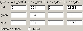 |
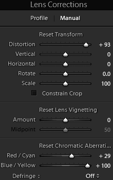
Inon UWL-H100
wide-angle converter and 24mm lens
Inon UWL-H100 28LD 0.6× wide converter mounted on Recsea S100
housing with LD bayonet port adapter.
Camera zoom setting: max. wide
(equiv. f = 24 mm). Aperture = f/5.6.
Geometry and aberration before correction
Geometry and aberration after correction
The adjustments made using
Lightroom are shown on the
right.
Note that Lightroom (version 3) normalises the width and height
transformations separately in such a way as to anchor the picture at
the corners. This does not strictly preserve the aspect ratio of the
original scene, but the error will not be noticeable in the majority of
applications.
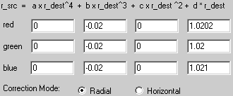
Also notice that Lightroom has not been able to make the ruler in the
picture completely straight. This is because this particular image
requires both 3rd and 4th
order corrections (see below).
Finally, once again, the blue-yellow fringing correction is
insufficient and some aberration remains. |
 |
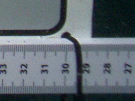
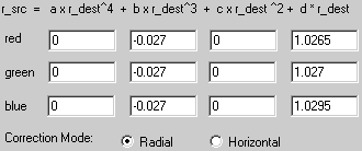
Here's the picture corrected using Pano Tools with finite 3
rd
and 4
th order coefficients.
| Radial correction
coefficients |
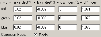 |
Overall, Adobe Lightroom is not as capable as Panorama Tools; but for
photographers who want to apply relatively minor image corrections for
non-technical purposes (i.e., the majority), the ease of use (of this
part of the program interface at least) is reason to favour it.
Technical users might also be inclined to try it first before resorting
to Pano Tools.
Further
information
Eliminating color fringing,
by Norman Koren (using Picture Window Pro):
© David Knight 2021.
Original article written in
2004 for the Cameras
Underwater info collection.
Updated 2006, 2011, 2012, 2018, 2021.
David W Knight asserts the right to be recognised as the author of this
work.
Photographs by David Knight and Steve Knight.
.