 |
The angle of coverage (or field of view) of a lens
By David W Knight.
Finding angle of coverage from focal length
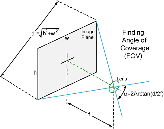
The focal length quoted for a camera lens is often an approximation. This is the source of the discrepancy in angle of coverage figures quoted by different manufacturers for a given focal length and image format, particularly in the case of wide-angle lenses, where small changes in focal length cause large variations in angle of coverage. The standard or 'nominal' figure quoted is the angle of coverage on the diagonal of the image format, with the lens focused at infinity. This means that the lens pupil (of an equivalent symmetric lens) is at a distance f from the film, where f is the focal length. The diagonal of the film format, d, can be calculated using Pythagoras's theorem (the square on the hypotenuse of a right angled triangle is equal to the sum of the squares on the other two sides).
For the 35mm film stills format (36 × 24mm):
d = √(36² + 24² ) = 43.3mm.
From the diagram below, note that an angle equal to half the angle of coverage has its tangent equal to half the format diagonal divided by the focal length; i.e.:
Tan(α/2) = (d/2) / f
Hence:
Angle of coverage (field of view, FOV)
| α = 2Arctan(d / 2f) |
where "Arctan" means "the angle for which the tangent is". Arctan (the inverse tangent) is also sometimes written as: Tan-1.
The formula derived above gives 46.8° for a 50 mm lens, 63.4° for a 35 mm lens, and 94.5° for a 20 mm lens (assuming the 35 mm film format). Note that these figures apply only to bare lenses. Any supplementary lens, flat underwater port, or dome port operated with the lens entrance pupil not exactly at the centre of curvature of the dome, will alter the coverage.
Effect of a flat air-water boundary
If the lens is situated behind a port, the change in coverage due to refraction at the air-water boundary must be taken into account. For a flat port, the modified angle of coverage α' can be obtained using Snell's law as follows:
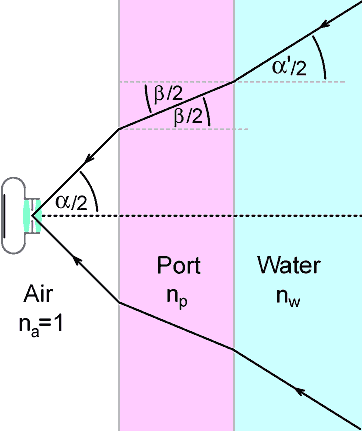
Referring to the diagram above, if the half-angle of coverage in air is α/2, then the new half-angle of coverage in the port material (β/2) is given by the expression:
Sin(β/2) / Sin(α/2) = na / np
Where na and np are respectively the refractive indeces of the air and the port material.
The expression can be rearranged:
np Sin(β/2) = na Sin(α/2) . . . . . . . . (1)
Similarly, the half-angle of coverage in the water (α'/2) is given by:
Sin(α'/2) / Sin(β/2) = np / nw
or
nw Sin(α'/2) = np Sin(β/2)
(α' should be pronounced "alpha prime", where a prime indicates a modified version of an original quantity without a prime).
Substitution using (1) gives:
nw Sin(α'/2) = na Sin(α/2)
i.e., the effect of the intervening port port material is cancelled, and the port itself has no effect on the angle of coverage (although it does alter the effective position of the lens entrance pupil as seen from outside the housing).
If we assume that the refractive index of air (na) is 1 we get:
Sin(α'/2) = Sin(α/2) / nw
where nw is about 1.334 for fresh water and 1.339 for sea water
Rearranging gives the working formula:
| α' = 2 Arcsin[ Sin(α/2) / nw ] |
(divide the 'in air' angle of coverage by 2, take the sine, divide the result by the refractive index of water, take the inverse-sine, multiply the result by 2).
Using the formula above; the coverage of a 35 mm lens (for example) is reduced from 63.4 to 46.5°, giving it almost exactly the same perspective as a 50 mm lens in air.
Note that for a dome port, when the entrance pupil of the lens is located exactly at the centre of curvature of the dome, the angle of coverage is the same as in air.
Diagonal coverage of lenses on the 35mm format
This table applies to lenses designed for use in air. The 35 mm format diagonal is 43.267 mm. The refractive index of (sea) water was taken to be 1.339 for the underwater coverage figures.
|
|
|
|
|
|
|
|
|
|
|
|
|
|
|
|
|
|
|
|
|
|
|
|
|
|
|
|
|
|
|
|
|
|
|
|
|
|
|
|
|
|
|
|
|
|
|
|
|
|
|
|
|
|
|
|
|
|
|
|
|
|
|
|
|
|
|
|
Angle of Coverage when not focused at Infinity
If you need to know the exact coverage of a camera system in a particular application; you should be mindful of the fact the angle of coverage is reduced when the lens is focused closer than infinity, and is reduced substantially when making macro photographs. The reason for the change is that the iris of the lens has moved away from the film plane to a new distance f+x, where x is the lens extension required to bring the image into focus. For a 1:1 macro photograph, the distance f+x is equal to 2f, and so it should be obvious that the capture angle will be much reduced from its infinity value. The modified coverage formula becomes:
Angle of coverage for lens extension x,
α(f+x) = 2 Arctan[ d / 2(f+x) ]
Calculating actual coverage thus requires information which may be difficult to determine (measuring the lens extension is tricky), but there is a pragmatic solution (see below) which stems from the fact that the formula given earlier can perfectly well be used backwards.
Estimating angle of coverage
Assuming that you are interested in determining exact coverage for some scientific purpose, you will probably be more interested in the horizontal or vertical angle than in the more marketing-orientated diagonal figure. All you have to do is lay a ruler or a tape-measure across the subject area, take a photograph of it, and record the distance from the subject plane to the lens entrance pupil (the point where the iris appears to be when you look into the front of the lens). If d is the width, height, or diagonal of the subject plane (whichever you want to use), and a is the distance from the subject plane to the entrance pupil, the new formula is:
Angle of coverage for lens-to-image-plane distance a,
αa = 2 Arctan(d / 2a)
Effect of Radial Transfer Function on Coverage Determination
 Barrel (fisheye) distortion |
 Pincushion distortion |
In all lens systems, the relationship between radial distance from the lens-axis in the object and radial distance from the lens axis in the image is non-linear (in principle if not in practice). This non-linear relationship gives rise to barrel distortion in wide-angle lenses (unless extra lens elements are included to correct for it), and pincushion distortion in underwater optical systems that have a flat air-water boundary (port) in front of the lens. Both phenomena can be understood by considering what happens when a photograph is taken of a graduated ruler that passes through the centre of the picture: If a lens suffers from barrel distortion, the ruler graduations in the image will get closer together the further they are away from the lens axis. If the lens suffers from pincushion distortion, the ruler graduations will get further apart. Now; consider what happens if you take a photograph of a rectangular object that nearly fills the frame. The top and bottom, and left and right, edges of the rectangle will be closer to the middle of the picture (the lens axis) than the corners. Therefore, if the lens exhibits barrel distortion, the corners of the rectangle will appear to have been dragged in, while if the lens exhibits pincushion distortion, the corners will appear to have been pushed out.
The relationship between what you put into a system and what you get out is called the transfer function. Hence the relationship between distance from the lens axis in the object and distance from the lens axis in the image is called the radial transfer function. This transfer function for simple lenses follows an approximately cubic law; which means that for light rays that have only a small angular displacement from the lens axis, the associated scale distortion will be barely perceptible, but as the angular displacement increases, the gradient of the transfer function will become progressively steeper and the scale distortion will soon become severe. It is for this reason that normal and telephoto lenses show little distortion (and are in any case relatively easy for the designer to correct), whereas wide angle lenses, and especially zoom lenses set in the wide-angle position, will often show pronounced distortion and are inherently difficult to correct.
Scale distortion, of course, will affect any measurements that have to be made from a photograph. If, for example, you take a photograph of a ruler that is horizontal in the picture, and try to use this measurement and the picture aspect ratio to find the diagonal distance, you will get the wrong answer! You can only calculate the diagonal distance if you know the radial transfer function, and you're unlikely to have that information unless you designed the entire lens system yourself. The pragmatic solution therefore is to apply a radial correction. The radial correction process is simply a matter of multiplying the direct distances of each of the pixels from the lens axis by a factor calculated from an inverse transfer function (which is determined by trial and error); and the only guidance needed in obtaining this function is that it should cause the image to reproduce straight lines and right-angles correctly (rectilinear correction). Once the correction has been performed, scale distortion is removed, rectangles are rectangles once more, and the image becomes a nice friendly linear two-dimensional space.
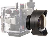 |
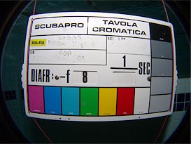
Example Ikelite made a 3" radius dome port for the Olympus C-5060 camera and the Olympus WCON-07C 0.7× wide-angle converter lens. Peter Schulz posed the question; 'what coverage do you get if you leave out the wide-converter and just use the port with the bare camera lens?' |
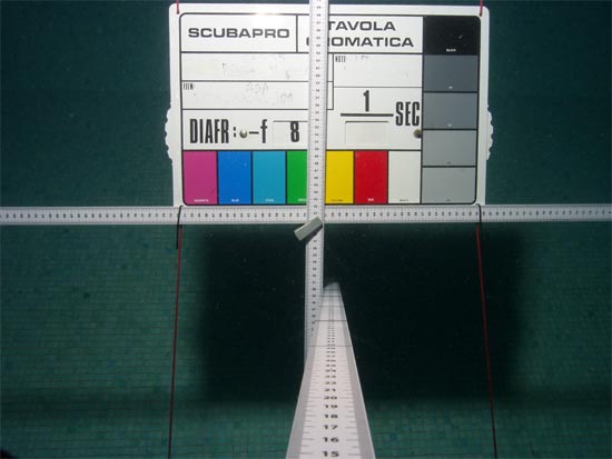
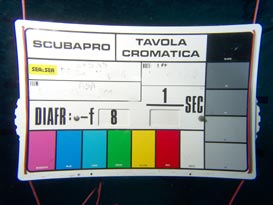
The ruler seen protruding from the camera was strapped to the lens port casing with cable-ties, and the scale zero was adjusted to be in the same plane as the entrance pupil with the equipment submerged, as far a could be determined by eye (about ±1 cm). In this photograph, the object plane is 88.2 cm wide after radial correction, and the distance from the lens pupil is 74±1 cm. Since the aspect ratio of the C-5060 CCD sensor is 4:3. this makes the height of the object 88.2 x 3 / 4 = 66.15 cm, and the diagonal, by Pythagoras' theorem, is √(88.2² + 66.15²) = 110.25 cm. The angle of coverage, using the formula given earlier is thus 73.4°, but before accepting this figure we should consider the errors inherent in the determination. By far the greatest source of error in this case lies in the determination of the entrance pupil position. There will be some error in the diagonal measurement also, due to possible imperfections in the radial correction function, but since the diagonal measurement will also vary as the lens is moved backwards and forwards, this can be lumped with the error in the entrance pupil distance. Hence if we increase the uncertainty in the entrance pupil position to about ±1.5 cm, this should provide a reasonable confidence interval (standard deviation) for the measurement. The edges of this confidence interval can be found by calculating the angles of coverage for distances of 74+1.5 cm and 74-1.5 cm, and the two values so obtained are 72.3° and 74.5°. So the determined angle of coverage is 73.4 ±1.1°.
Note that the lens system is focused at 74 cm for this determination (the camera lens is actually focused on a nearby virtual image created by the dome port). Due to a change in the lens focusing extension, the angle of coverage will be very slightly wider when the system is focused at infinity.
The Olympus C5060 + WCON-07c combination is used as an example in the radial correction article. In air, this system has a coverage of 97°, but when used underwater with a flat port, the coverage is only 68°. Using the camera underwater with a dome port and no wide-converter turns out to give a greater FOV (73°), and the flat port also produces severe chromatic aberration. If the wide converter is used with the dome port, the FOV is, of course, approximately the same as in air.
 DWK
DWK© D W Knight. 2001, 2006, 2012. Updated Feb. 2018.
David Knight asserts the right to be recognised as the author of this work.