 |
Pixels and Resolution
A picture is worth a thousand words, but requires a larger file size.
Image pixels:
In a colour display or a printed image, a pixel (picture element) is a dot or small area of the picture that is large enough to carry the three attributes hue, colour saturation, and brightness but too small to carry any detail. An electronically produced picture is made up of an array of pixels and is normally viewed from a distance such that the underlying structure is no longer visible.
| In practice, image pixels are usually composite: the pixels of a TV picture being composed of areas of red, green, and blue illumination; and the pixels in a printed image being built up from groups of cyan, yellow, magenta, and black ink spots. Any structure within a pixel will average to the required combination of brightness and colour when viewed from a suitable distance. |
Pixel data:
In the context of photography, the information used to create a displayed image is usually extracted from a data file. The data file therefore contains, or can be decompressed in some way to provide, a set of numbers representing each pixel in the image. In an uncompressed RGB image file, a pixel is represented by three numbers, these being related to the brightness values for red, green, and blue at a particular point in a video display. In an uncompressed CMYK image file, a pixel is represented by four numbers, these being related to the amounts of cyan, magenta, yellow, and black ink to be applied to a particular point in a printed picture. Other representations are also possible, and we can, of course, convert between representations for such purposes as viewing CMYK files on a monitor screen, or printing RGB files onto paper.
The maximum amount of detail that can be recorded in an image file is dependent on the number of pixels, but the number of pixels should not be used as a measure of resolution. The relationship between pixels and actual sensor resolution will be discussed shortly, but the most obvious way in which the pixel count can become divorced from recorded detail lies in the fact that files can be re-sized. If a file is re-sized to reduce the number of pixels in it, detail may be lost, but if a file is re-sized to increase the number of pixels, new detail cannot be created (although subjective improvements can be obtained).
Camera pixels:
Digital cameras also have pixels. They must have because the manufacturers say they do, and the pixel number is usually assumed to be a measure of resolution. It is therefore tempting to think that if the pixel size of a file produced by a camera is set to be the same as the number of pixels in the camera sensor, then the native resolution of the camera will be carried through to the final image. Unfortunately, this will not be the case, for two very important reasons:
 The
resolution
of the camera sensor is not related to the resolution of the
lens. A
camera
does
not necessarily have identifiable RGB pixels.
The
resolution
of the camera sensor is not related to the resolution of the
lens. A
camera
does
not necessarily have identifiable RGB pixels. The pixels in the camera output are created by interpolation from raw sensor data and so cannot be assumed to be directly related to the individual sensor elements. Furthermore, cameras do not have to have their light sensors arranged as RGB triads, and so it does not always make sense to think of a single colour sample as a third of a pixel. This paradox has gradually led to a consensus within the camera industry, which is that the pixels of cameras should be defined differently to the pixels of files and images. Specifically:
The
number
of pixels stated for a digital camera is the total number of
light sensing elements (red
+ green
+ blue).This number is, of course, considerably larger than the number of RGB pixels corresponding to a notional 'native' resolution, but if a single number is to be used as an indicator of camera quality, it is the only measure that gives a reasonably fair comparison between the various different sensor architectures.
| Filter-mosaic
cameras Most digital cameras use a two-dimensional array of light sensors and colour filters arranged in a pattern known as a 'Bayer mosaic' (US Pat. No. 3971065). The filter mosaic has twice as many green filters as it has of red and blue, i.e., an 8M pixel camera has 4M green, 2M blue, and 2M red sensors. |
 |
| The normal maximum output file size for a Bayer mosaic camera however, usually has as nearly as many RGB pixels as there are camera pixels, RGB pixels being obtained (notionally, ignoring processing) by going to every intersection between four camera pixels and taking the adjacent light values (a red, a blue, and the average of two green samples). Hence the output RGB pixels are unique, but share samples with other pixels; and the maximum file size should not be taken to be indicative of sensor resolution. |  |
* The recipe for simulating white light using the three additive primary colours is 0.59G + 0.3R +0.11B. Hence the green channel, being the main contributor, carries more luminance information than the other colour channels.
3-Chip cameras:
In a 3-chip camera, light from the lens is split into three, filtered, and sent to 3 monochrome imaging chips, one each for red, green, and blue. The native luminance resolution of such a camera is approximately equal to the number of sensing elements in the green channel. The colour resolution will be slightly less than the luminance resolution because there is a limit on the accuracy with which the three colour images can be superimposed. The 3-chip imaging method was once preferred as a superior alternative to the Bayer mosaic for high-quality video cameras (i.e., relatively low resolution but fast readout cameras). In high resolution systems however, it is the optical splitter prism rather than the pixel number that places limitations on the ultimate resolution obtainable. Consequently, as pixel numbers and in-camera processing power have increased, single chip imaging methods have become universal.
The Foveon X3® sensor:
| The Foveon X3 has its blue, green, and red sensor arrays in different layers of the chip, with the sensing elements stacked in perfect registration. Hence the sensor does have identifiable RGB pixels, even though the number of 'camera' pixels will normally be reported as the total of red + green + blue sensor elements. |
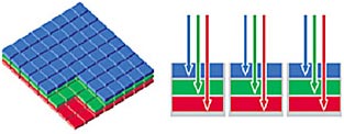 Illustration by kind courtesy of Foveon Inc. All rights reserved. |
* The X3 Quattro sensor is a modified form having more luminance than colour resolution. It has four times as many sensor elements in the top layer compared to the 2 layers beneath.
Line-scan cameras (scanners):
In a typical scanner, a portion of the image is focused onto a strip-sensor, and the sensor is moved in small steps in order to acquire the whole image. The sensor usually has 3 strips (one each for red, green, and blue), each consisting of a linear array of photosensors. An RGB image is built up line-by-line by stepping the 3 different colour recording strips into position in turn. Since each dot is sampled three times, generally with near-perfect registration (in single-pass scanners at least), luminance and colour resolutions are practically identical. If the scanner software is set to give an output file at the scanner's native (i.e., optical) resolution, each pixel in the output is directly traceable to a point in the image (neglecting the various processing operations that may be carried out between image acquisition and file creation).
Sensor comparisons:
In the real world, fine detail does not have to be in black and white. Consequently, imaging devices that give equal resolution in luminance and colour (X3 and scanners) have the potential to give higher quality colour pictures for a given number of 'native' RGB pixels than imaging devices that have reduced colour resolution (mosaic and 3-chip). Hence we cannot even use 'equivalent native RGB pixels', or 'file size just big enough to capture all of the information' as an objective measure of comparative resolution, because the information captured varies in quality. We can illustrate this point by comparing two hypothetical 10.2M pixel cameras, one based on the Foveon X3 and one using a Bayer mosaic:
|
|
|
(equivalent native RGB pixels) |
(equivalent native RGB pixels) |
|
|
|
|
|
|
|
|
|
|
If we exclude subjective criteria, the X3 obviously gives the best resolution, but if we accept that detail is less important in areas of high colour saturation, the two image capturing methods are about the same. Thus defining the number of camera pixels as the total number of light sensing elements gives a simple method of comparison, and has the virtue that the pixels so defined are related to physical light sensors. The problem with simple comparisons however, is that they are sometimes far too simple. One major limitation of the mosaic system is that it produces interpolation artifacts (false detail), and cameras often incorporate a blur filter in order to reduce such artifacts to an acceptable level. A blur filter reduces resolution in the raw camera output, and although this loss can be restored by a process known as deconvolution, deconvolution is often too computationally intensive to be carried out in the camera. Also, one of the many ways in which camera pixels become divorced from output pixels is that the raw sensor data is usually subjected to a noise reduction process. Such processing also reduces resolution slightly and may also generate artifacts, and so low sensor noise is a definite advantage.
On the issue of whether overall (full colour) resolution is truly less important than luminance resolution, we can at this point allow some consideration of lenses to creep into the discussion. All lenses exhibit at least some minor chromatic aberration, this being due to their inability to provide exactly the same amount of magnification at all wavelengths in the visible spectrum. The problem manifests itself as colour fringing in off-centre picture detail, and is of particular relevance to underwater photographers because it is unavoidable when using an air-corrected lens behind an air-water boundary. It can however be substantially reduced using software, by a process known as radial correction (see lens correction article); but by a parallel argument, it is also true that maximum resolution usually cannot be obtained unless radial correction is applied. As we move away from the centre of an image projected by a lens, we expect any detail with a strong luminance component (e.g., a small white spot) to be turned into a detail with strong colour components (i.e., red, green, and blue spots either separate or partially overlapping). In the correction process, which involves re-mapping the red and blue images to superimpose them properly on the green image, fine colour detail is converted into fine luminance detail. Consequently, if we fail to preserve the same amount of detail in all colour channels of the image recording device, we lose some of the ability to extract fine luminance detail from the data.

From a software point of view, radial correction for lenses working in air requires only a knowledge of the lens focal length (zoom) setting, and to a lesser extent, the focus setting. This information is easily recorded at the time of picture taking, and so provision for radial correction can (at least in principle) be included in the camera firmware or the raw-file conversion software. Underwater photographers however, being in the business of adapting air-working lenses for underwater use, will need to apply their own corrections.
Sensor resolution:
Resolution (resolving power) is the ability to record or represent detail. A physically meaningful measure of resolution can be given in terms of the maximum number of parallel lines that can be reproduced over a given distance; a grid of lines being the worst-case test. In a monochrome camera sensor, or a colour imaging system having superimposed R G and B pixels, we can relate resolution in lines to the number of sensing elements in a strip perpendicular to those lines by observing that lines cannot be resolved unless there are enough sensing elements to register all of the alternations between light and dark. Therefore, the limit of resolution is reached at the point at which there are just two sensor elements for every line. This situation is represented in the diagram below, which shows what happens when a test pattern of lines is projected onto a sensor at a magnification that makes the spacing between the lines equal to the distance between two sensor elements.

If the system is operating at something close to the maximum resolution of the lens, the lens will blur the detail and project a pattern of smoothly alternating light intensity onto a row of light sensors. Each sensor records the average intensity of the light collected over its area, and so the output will be a row of alternating dark grey and light grey pixels. Thus, although there is some loss of contrast caused by the lens in this case, the output is a faithful reproduction of the original detail. Notice however, that in the diagram above the brightness peaks were lined up so that they fell in the middle of their respective sensors. When the pattern is moved sideways by one half of the pixel spacing an entirely different result is obtained:

Now the peaks and troughs of the projected image lie on the boundaries between the sensor elements. Hence if one sensor element records the average of the transition from lightest to darkest, the one next to it will record the average from darkest to lightest, and the result will be a mid-grey in either case. Hence if we move the camera or the test card, the contrast in the detail recorded at maximum resolution will vary between zero and some maximum value. Thus we may deduce that two pixels for every line of resolution is an absolute minimum, and represents the point at which all contrast in the resulting image may just be extinguished. Also, we must note that there is no rule to say that the lines in the resolution test pattern must be horizontal or vertical, and if we want to state the resolution for lines of arbitrary orientation, we must take the worst case, which is the number of pixels per unit length along a line at 45° to the horizontal or vertical. The diagonal of a 1 × 1 square is √2. Therefore, if a monochrome sensor (or a colour sensor having superimposed R G and B pixels) has p sensor elements per mm in the horizontal and vertical directions, the absolute maximum resolution in lines/mm will be p/(2√2).
Unfortunately, we cannot use this simple notion of image capture to deduce the resolving power of a Bayer mosaic sensor, except to note that its luminance resolution will be, at best, about the same as that of a monochrome camera with half as many pixels. We cannot assume moreover, that best performance will always be obtained, it depends on the sophistication (and hence the cost) of the optical system and the software that converts the raw data into RGB pixels. In particular, a blur filter is required in order to ensure that no detail in the image projected onto the sensor is smaller than the area of 4 camera pixels (if a detail is too small it will fall selectively on a single colour pixel and be recorded incorrectly as colour information), and intensive calculation is required in order to reconstruct the full resolution image from the raw recorded data.
The sensor resolution, of course, does not tell us what the overall resolution of a camera will be. The final limiting factor is lens resolution, which is beyond the scope of this article but well covered elsewhere. See for example, the excellent website of Norman Koren
www.normankoren.com
and particularly the tutorials on image sharpness and MTF
www.normankoren.com/Tutorials/MTF.html
See also: Dick Lyon's photo technology lectures.
We can however offer a general rule based on sensor format size:
The resolving power of lenses is not infinitely scalable. Therefore when a lens is used to project an image onto a surface, the maximum amount of detail that can be preserved is a function of the size of the image. Consequently, if a large format camera and a small format camera are both used to produce a picture of the same size, the large format camera will give the greatest resolution in the final picture (assuming a sufficient number of pixels and well designed lenses in both cases).
 DWK, Nov 2004, Updated March 2018.
(Thanks to Dick Lyon of Foveon Inc. for helpful advice and suggestions in the writing this article).
© David W Knight, 2004, 2018
© 1998-2004 Foveon, Inc. Foveon X3 and the X3 logo are registered trademarks of Foveon Inc.
| |