Optical
Magnification
By David Knight
Thin lens formulae
For those who use cameras and lenses (as apposed to those who design
them), most calculations relating to field-of-view (FOV) and
magnification can be performed by using the concept of the idealised
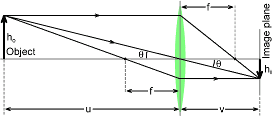
equivalent symmetric thin lens. A converging (bi-convex) lens of this
type is depicted below, with its attendant ray diagram. Note that,
since the lens is symmetric, it works the same regardless of which way
the light is travelling. Thus it has two focal points, one on
each side, both at distance f (the focal length) from the plane of the
lens. The focal point is defined as the point at which an ideal lens
brings light from infinity to a focus.
The idealised converging lens has the following
properties:
1) Light rays travelling parallel to the axis are deflected in such a
way as to make them pass through a focal point (and light rays passing
through a focal point are deflected to run parallel to the axis)
2) Light rays passing through the centre of the lens are undeflected.
The first condition follows from the
definition of the focal point. The second condition arises because the
front and back surfaces at the centre of the lens are parallel, so that
the deflection of the ray as it enters the glass is reversed as it
leaves the glass. Since the lens is thin (and especially if the ray is
nearly perpendicular to the surface, the lateral displacement on
passing through the glass is negligible. Taken together, the two
conditions give rise to the
thin lens formula:
1
u |
+ |
1
v |
= |
1
f |
. . . . . . . . |
(1) |
where u (the 'object distance') is the distance from the object to the
lens plane, and v (the 'image distance') is the distance from the image
to the lens plane. 'Proof' of this relationship is given by the
boundary conditions (i.e., by what happens at the extremes of the
possible values of u and v). Thus when u
→∞,
1/u
→0
and v=f. Similarly, when v
→∞,
1/v
→0
and u=f. In other words, the formula arises because the lens brings
light from infinity to a point.
The magnification due to the lens is
defined as the height of the image divided by the height of the object:
m = h
i / h
o
but, looking at the diagram we can see that:
Tanθ = h
o / u = h
i
/ v
which tells us that
h
i / h
o = v / u
i.e.;
We can also obtain more formulae for the magnification as follows:
Firstly, multiply equation (
1)
throughout by v. This gives:
(v/u) + (v/v) = v/f
i.e., substituting for v/u using (
2):
m + 1 = v/f
hence:
| m = ( v / f ) - 1 = (v - f) /
f |
(3) |
also, we can multiply equation (
1)
throughout by u, which gives:
1 + 1/m = u/f
i.e.,
m = 1 / [ (u/f) -1 ]
which, upon multiplying top and bottom of the right hand side by f
gives:
Unit
magnification
From equation (
2)
we can see that unit magnification (m=1), also known as the 1:1 macro
condition, occurs when v = u. If we put this into equation (
1)
we get:
2 / u = 1/f
i.e.:
u = v = 2f
Unit magnification occurs when the lens is placed at a distance of
twice the focal length from the image plane (note however, that this
rule only applies to symmetric lenses).
Practical
camera lenses
Unfortunately, simple thin lenses do not bring light rays from a point
on the object to a perfect point in the image. There are numerous
optical defects, such as spherical aberration and chromatic aberration,
and these place a limit on the sharpness of the resulting image. Hence
lens designers add extra elements (i.e., extra simple lenses), with a
view to cancelling the various aberrations to some acceptable degree.
These attentions bring the system closer to the ideal in terms of ray
convergence, but the resulting compound lens is no longer thin.
The camera lens designer must also work
to the specification of the lens mount, which means that some lenses,
particularly wide-angle types, cannot be made symmetric when the
distance from the exit aperture to the image plane is greater than the
required focal length (the lens must be able to focus at ∞).
A further consideration is that digital camera sensors suffer from
sensitivity fall-off for light rays arriving at angles far from the
perpendicular, and the solution to this problem is to design the lens
so that emerging rays appear to come from a point a long way from the
sensor (often well in front of the camera).
The aperture towards which light rays
from outside the camera must be directed in order to form an image is
called the 'entrance pupil'. The aperture from which light rays appear
to emerge is called the 'exit pupil'. The pupils usually
correspond to the apparent position of the iris when looking into the
respective side of the lens (but not necessarily to the physical
position of the iris). The practicalities of camera lens
design, as well as often demanding that the front and back focal
lengths are different, almost invariably demand that the entrance and
exit pupils do not lie in the same plane. The result is that the
object-side (front) and the image-side (back) optical systems become
physically disconnected, as shown in the diagram below.
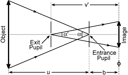
Note that, in general, the object side field-of-view
(α) does
not have to be the same as the image side FOV (α'). In
particular, in the case of a wide-angle lens, it is usually important
that α' << α (to
avoid sensor fall-off, to allow room for an SLR mirror, etc.). The
designer nevertheless can calculate the angle α that
corresponds to the image just filling the diagonal of the format,
and this can be converted to an equivalent symmetric-lens focal length
using a formula given in the
angle of coverage
article, i.e.:
f = d / [ 2 Tan(α/2) ]
where d is the format diagonal. Note that f is a true focal length in
the sense that a light ray passing through the front focal point (on
the object side) will emerge parallel to the axis on the image side.
The lens however, will not necessarily focus light from infinity (on
the object side) to a point at a distance f (on the image side) from
either the entrance or exit pupil.
The consequence of the spatial
disconnection between the front and back optical systems is, from the
camera user's point of view, surprisingly minimal. We can remain
blissfully unaware of what goes on inside the camera and perform
calculations relating to external optical systems (lens ports,
supplementary lenses, etc.) on the basis that there is a symmetric thin
lens of focal length f located at the entrance pupil. The only caveat
is that it is no longer possible to determine the position of the image
plane from the object distance and the front focal length f. We do need
to know where the image plane is however, because it dictates where the
entrance pupil will end up when we mount the camera (e.g., on its tray
inside an underwater housing), and because the distance markings on the
lens (and the minimum focusing distance) are specified relative to the
image plane. For that reason we need to determine an additional
parameter b (the back focal distance), which can sometimes be obtained
from the lens literature, but must otherwise be estimated.
On cameras with interchangeable lenses,
the image plane (also called the 'focal plane') is often marked with
the symbol

. The
reason why optical measurements are
given relative to the image plane is that it is a fixed reference
relative to the lens mount, whereas the entrance pupil moves as the
lens is focused or zoomed.
A final point, of which most
photographers will already be aware, is that since we don't need to
know the details of the back optical system, we are at liberty to use
any value of format diagonal we care to choose in order to obtain the
focal length equivalent to the FOV. A common choice is to use
the diagonal of the 35 mm stills format (43.267 mm), so that our
equivalent focal lengths correspond to familiar properties
(<28 mm is wide, ca. 50 mm is normal perspective, 80 mm is portrait
and ≥135 mm is telephoto). We can also, for every
format, work out a 'crop factor', which is a number by which the actual
focal length of a lens must be multiplied in order to obtain the 35 mm
equivalent focal length. The crop-factor for the Four-Thirds format,
for example, is 2; which means that (say), a 50 mm lens acquires a 35 mm
equivalent focal length of 100 mm.

DWK
© David W Knight 2012, 2018.