Artificial
Lighting for Underwater Photography
By David Knight
Apart from the need to make the equipment waterproof, the major
differences between photography in water and photography in air are due
to the fact that water absorbs and scatters light. Human vision adapts
automatically to this change of environment, but camera systems require
help and persuasion if they are to produce good results. The specific
problems that have to be addressed are as follows:

Water absorbs light across the whole of the visible spectrum. Water may
look clear in a drinking glass, but light absorption over distances of
several metres is significant. Hence the underwater environment is
dark, artificial lighting is often needed, and flash and video lights
are not as effective as they would be in air.
Water absorbs light at the red end of the spectrum more strongly than
it absorbs light at the blue end. Water may look colourless in a glass,
but a glance at a swimming pool shows that it imparts a
cyan
cast to light that travels any appreciable distance through it.
Water usually has particles suspended in it; from small solid
particles, organisms, and gas bubbles, which give the impression of
fog; to large fluffy particles that give the impression of a blizzard.
The brain processes visual information to enable us to see through
partial obstructions, but the processing relies on stereo vision and
movement and is much less effective when we look at two-dimensional
still images.
These additional factors change the rules considerably in relation to
lighting intensity requirements, working range, white balance, and
lighting position. It might also be said that 'lighting technique' not
only encompasses the use and positioning of lights, but the image
adjustments that can be carried out before or after the event in order
to restore colour balance and contrast. With the latter in mind, those
interested in obtaining professional quality results should use cameras
that can provide output in a 48 bits-per-pixel (48 bpp, 16 bits per
colour channel) file format (e.g., RAW), the point being that an image
file with 4096 brightness levels for each primary colour (rather than
the usual 256) can be subjected to large adjustments without
significant quality loss.
Reduced Guide
Number
Flash illumination underwater no longer follows the inverse-square law
on which 'in air' exposure guide tables are based. At a flash to
subject distance of about 1 metre, the guide number is reduced to about
a third of its 'in air' value. At greater distances, the guide number
is reduced even further, and only when the light source is very close
to the subject does the guide number begin to approach its 'in air'
value. Nowadays, we don't worry about guide numbers too much, taking
care of exposure by looking at the image histogram or by using TTL
flash, but it means that a powerful light source is needed if an
appreciable range is to be obtained.
Colour Cast
What is meant by 'appreciable range' may also come as a surprise, the
issue being that clear water acts as a strong cyan-blue filter. We need
to remember here that white light is a mixture of all the colours of
the spectrum. The problem is that the different colours are not
absorbed equally by water. Red is absorbed particularly strongly,
leaving pictures taken at intermediate range with a cast of the
complementary colour, i.e.
cyan.
For very long range (10 m or more), both red and green are absorbed and
the only colour substantially recorded is blue. In the latter case,
little or no colour information is present in the picture, and the best
presentation may well be obtained when the colour saturation is turned
down to zero and the picture is reproduced in black and white.
In clear water (free from green algae
or brown mud)
the red component of white light is reduced relative to the blue
component by about 1 EV (i.e. halved) for every 2.5 m of light path.
Since the light has to travel from the lighting unit to the subject,
and then from the subject to the camera; if a light source is aimed
from the vicinity of the camera, a photograph taken at a distance of
1.25 m has its red component reduced by the equivalent of 1 f-stop. In
the old days of direct-projection transparency film, this meant that
the maximum flash illumination range was in the order of 1 to 2 m, and
the strong cyan cast was taken to be a fact of life. Compensation was
possible at the printing stage, and nowadays, we can adjust the image
data to pull out the cast; but electronic noise can be a problem if the
gain of the red channel is adjusted too far, and so the trick in
producing clear colourful pictures still lies in working at short range.
Backscatter
A particular problem arises when using artificial light in cloudy
water, and is exactly analogous to that of trying to use full-beam
headlights when driving in fog. Light is scattered back by the
suspended particles, and the subject can sometimes hardly be seen at
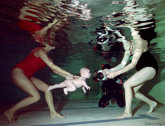
all. Natural water is always a little cloudy, and swimming pools are
only clear when properly maintained*; so if high clarity is required it
is important to check the state of the water and keep extraneous
swimmers and divers away from the location for a few hours so that
particles can settle. For poor visibility that cannot be avoided, the
problem is reduced by aiming the camera and light source from different
directions (the point being to light only the subject and not the
suspended particles between the subject and the camera); and by working
at very short range (i.e., by using wide-angle and macro lenses).
Remedial action at the post-processing stage involves adjusting the
image black-point (Photoshop: levels) to crush-out the general
background fog and increase contrast; and using the cloning stamp to
remove any distracting white spots.
*
Sand filtration alone is not enough. Perform a good backwash a few
days before a shoot and add some flocculating agent (e.g. Aluminium
Sulphate) to the input side of the filter.
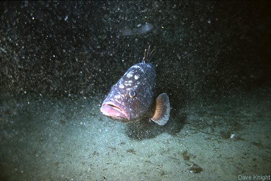
 BACKSCATTER BACKSCATTER
Above: Picture spoilt by silt
kicked-up by
divers who had visited the site immediately prior to the shot. The
suspended particles are barely noticeable to the diver, but firing a
flash lights them up.
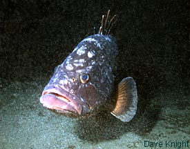
Right: the same image retouched
using the
Photoshop cloning stamp, with the black-point adjusted slightly to
disguise the general fogginess.
|
 |
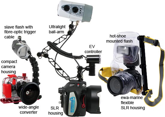
Backscatter, even in water that appears to be clear to the naked eye,
is a severe problem when using the internal flash of a compact camera.
It is for this reason that an external lighting unit, which can be
moved away from the lens as necessary, is recommended whenever
artificial lighting is to be used.
In recent years, the sensitivity of
digital cameras
has improved to the point where it is possible to obtain good
photographic exposure using a video light. This is
particularly
the case for cameras having a fairly large sensor area, i.e.,
Four-Thirds, APS-C and full frame 35 mm formats. It is worth
noting therefore, that it is easier to make the lighting adjustments
required to minimise backscatter when using a video light (as opposed
to flash), for the simple reason that the setting-up of the photograph
is done with the light source that will be used when taking the
photograph. All of the discussion below relating to flash
lighting position and direction applies equally to video lights.
Lighting
position
In the dim and distant past there was something called 'standard
lighting', which involved having the flash unit mounted on an arm and
tray and positioned above and to the left of the camera. Whoever coined
the term it is not politic to recall, because this lighting position is
mostly a bad idea. It might better be called the 'apathetic' or 'not
very good at controlling my buoyancy' lighting position, because the
immediate reaction to any picture so produced is "It looks like it was
lit from the left". The point is that it was not intended that the
flash unit should be routinely fired from that position, the clue being
in the fact that there is a
coiled cable connecting
it to the
camera. The attachment of the arm to the tray allows the diver to get
into the water with a hand free to trim buoyancy. After that, the
lighting arm is released and the flash is positioned by hand, generally
in anything but the so-called 'standard' lighting position.
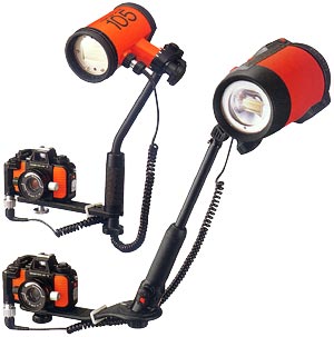
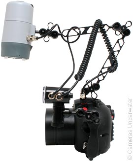
"STANDARD"
LIGHTING ?
Nikonos V camera shown with SB105 and SB104 speedlights. The flash arm
can be detached from the camera tray by loosening a nut or by pressing
a button. The coiled cable can be made to extend to about 2 m. |
 |
Ball arms
For a small compact camera, a standard arm and tray is adequate, but
not necessarily optimal. For something bulky like an SLR housing
moreover, the camera needs to be controlled using both hands, and there
is no spare hand to hold the lighting unit. The solution is the
fully-articulated ball-joint arm, which permits nearly all of the
lighting positions that are possible by hand-holding, and will keep
the light source rigidly positioned relative to the camera.
| Ball arms were invented
a long time ago,
but manufacturers took a while to perfect their designs. There were
many products that couldn't support the weight of a medium-sized flash
unit in air and tended to incur damage to the balls if the clamps were
done up tightly. One company got it right first off however, and that
was the diving equipment manufacturer Oceanic. The trick was to use a
ball of 1" (25.4 mm) diameter, and some old-timers still call this ball
size the 'Oceanic ball' to distinguish it from the smaller sizes that
didn't work properly. Oceanic pulled out of the underwater photography
market in the 1980s, but the design legacy remains in that the 1" ball,
or its metric equivalent 25 mm, has been widely adopted. In particular,
1" ball joint arm components are made by Ultralight, TLC and ikelite,
and 25 mm components are made by Inon, 10bar, and others; parts from the
inch and metric ranges being compatible by virtue of a tolerance in the
clamping system of about ±2 mm difference in ball sizes. |
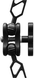
Ultralight ball joint |
Quick-release
Assembly and disassembly of a ball joint is a somewhat fiddly
procedure, and there are occasions when a ball joint arm does not
extend far enough or does not permit a particular lighting position.
Hence, to allow maximum versatility, and to facilitate dismantling of
the equipment for transport or to make it easier to change memory cards
and batteries, it is always desirable to have some means by which the
arm can be detached quickly from its base. Once again we call upon the
legacy of Oceanic, with its novel concept of allowing people who
actually used the equipment to be involved in the design process; their
offering, the Oceanic Shoe (universal shoe or
T-base), having been copied by numerous manufacturers and remaining a
perfectly good choice. |
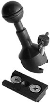
Oceanic Shoe
(Ultralight) |
An alternative to the Oceanic shoe is
the TLC
dovetail base, which is equally good; but better still are the ikelite
Quick-Grip and the Ultralight Quick-release handles, both of which
allow arm detachment at the press of a button.
Forward
Lighting
If there were to be a proper 'standard' (i.e., 'quite often gives a
good result') lighting position, it would be with the flash unit
mounted
directly above the camera lens and facing
forward. The
reason is that a picture that gets progressively darker as the eye
runs from the top to the bottom is psychologically neutral with regard
to lighting - i.e., the viewer is unaware of the lighting and sees the
subject first.
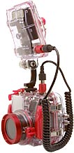
FORWARD
LIGHTING:
A sensible requirement for an underwater camera system is that it
should be able to provide light from directly above the lens without
the user having to hold the flash unit by hand. Note that,
for
the compact camera system on the left, the flash window is vertical
when the arm is bent inwards, i.e., the flash unit has been designed so
that the window is horizontal when the flash is in the off-side
"standard" lighting position. Having the window the wrong way
around reduces the coverage slightly, but the problem is readily solved
by fitting the flash unit with a diffuser. The disadvantage
of
the hot-shoe flash system on the right is that it can only
do forward lighting.
The forward lighting position is ideal for medium range working (0.5 -
3 m) in conditions of fair to good visibility. For this purpose, the
camera is best fitted with a wide-angle lens (or converter) having a
field of view (FOV) in the 63 – 100° range (35 mm
equivalent
focal length 35 - 18 mm when using a dome port), the point being to keep
the working range fairly short. Unless post-processing correction for
chromatic aberration is to be carried out, lenses of greater than about
63° FOV in air (35 mm equiv: 35 mm) are
not recommended
when
using a flat lens-port. Hence, choice of port is a factor in
determining how close the camera can be for a given size of subject.
In practice, of course, the lighting
unit should
preferably be tilted down to aim it directly at the subject. The more
expensive underwater flash units usually have a circular flash tube
with a spot beam-pattern targeting lamp mounted in the middle to
facilitate accurate aiming. The targeting lamp has the additional
benefit that it illuminates the subject so that the camera
auto-focusing system can operate in dark conditions. When using very
low levels of flash illumination, it is important that the targeting
lamp should be switched off during the exposure, otherwise its
illumination spot will be seen in the photograph. LED targeting lamps
can be switched off automatically during the flash exposure, but
old-fashioned filament lamps, being slow to respond, had to be switched off manually.
 |
 TARGETING
LAMP TARGETING
LAMP
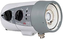
Shown is an ikelite DS-160 Substrobe, which has an LED targeting lamp.
When the flash is triggered, the lamp is automatically extinguished for
the duration of the flash exposure. |
The forward lighting position is also the natural choice for mixed
lighting (i.e., balanced natural and artificial light), sometimes
called 'fill-in flash'. Some cameras are able to compute the intensity
for for fill-in flash when a TTL flash system is used. When using a
manual flash system, the trick is to choose a shutter speed that
allows flash synchronisation, then meter for a natural light exposure
but choose an aperture setting that is somewhat smaller than the
metered value (between ½ and 2 stops usually). The flash
output
is then adjusted to make up the exposure shortfall. White balance is
normally set for flash or normal daylight in this case, and after
post-processing adjustment to set the colour balance for the principal
subject, the natural light contribution will retain a cyan or blue
colour cast.
 MIXED
LIGHTING: Here the colour balance has been adjusted in
post processing
to suit the foreground and the black-point has been adjusted to
disguise the fog. Note how the colour cast changes from cyan in the
mid distance to deep blue at infinity.
Bounce
Lighting
MIXED
LIGHTING: Here the colour balance has been adjusted in
post processing
to suit the foreground and the black-point has been adjusted to
disguise the fog. Note how the colour cast changes from cyan in the
mid distance to deep blue at infinity.
Bounce
Lighting
With a forward-facing light source, bounce lighting is possible in
clear shallow water because any light-ray striking a water-air boundary
at an angle of more than 48° from the perpendicular is
reflected
back into the water. This is the phenomenon of
total internal
reflection, the
critical angle
of 48° being dictated by the refractive index (n) of the water.
Bounce lighting will be inefficient if the surface is foamy or
broken-up by waves; but if the surface is reasonably flat, virtually
all of the light hitting the surface at greater than the critical angle
will be returned.
For bounce lighting, the subject should
be further
away than for normal forward lighting, and consequently a lens of
somewhat longer focal length than usual (e.g., 50 mm) should be used.
The point is that if the subject is too close, most of the reflected
light will fall behind it. Due to the long light-paths involved,
considerable adjustment of colour balance will be required in post
processing to restore the reds and yellows in the image, and so bounce
lighting is best accomplished using systems that can output 48 bpp
image data.
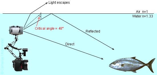 BOUNCE
LIGHTING: Light heading straight for the surface
escapes, but light rays that are not perpendicular to the surface will
undergo total internal reflection
if the critical angle is exceeded. The critical angle for fresh water
is 48.6°. For sea water, the critical angle is 48.3°
(i.e., it
is about 48° in either case).
MIRROR
EFFECT:
The water-air boundary acts as a highly efficient mirror for light rays
arriving at a shallow angle. This applies to light from the flash and
also to light returning from the subject.
Top Lighting
BOUNCE
LIGHTING: Light heading straight for the surface
escapes, but light rays that are not perpendicular to the surface will
undergo total internal reflection
if the critical angle is exceeded. The critical angle for fresh water
is 48.6°. For sea water, the critical angle is 48.3°
(i.e., it
is about 48° in either case).
MIRROR
EFFECT:
The water-air boundary acts as a highly efficient mirror for light rays
arriving at a shallow angle. This applies to light from the flash and
also to light returning from the subject.
Top Lighting
Like forward lighting, top lighting produces images that become
progressively darker from top to bottom. The difference however, is
that top lighting produces much stronger shadows. It follows, that top
lighting and forward lighting are not two distinct techniques, but
rather the two extremes of basic lighting technique. If the flash is
fired straight at the subject, a very flat image results. If the flash
is fired from above, the shadows bring out the three-dimensional nature
of the subject but can be distracting. Hence, it is usually sensible to
choose an intermediate direction that will allow some light into the
shadow regions.
One of the advantages of top lighting
however, is
that it greatly reduces the extent to which suspended particles in the
water between the subject and the camera are illuminated. As can be
seen from the diagram below also, there is a tendency for such
particles to be illuminated from behind, so reducing their propensity
to scatter light into the camera lens. Top lighting is therefore often
a good choice in conditions of moderate to poor visibility.
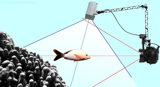
In the diagram above, a light cone with an angle of 100° is
depicted to be emanating from the flash unit, this being the stated
coverage figure for the model shown (ikelite DS-160) when fitted with
its supplied diffuser. In reality however, flash units do not have a
sharp cut-off at the edge of the useful illumination field, which means
that some of the light from the flash may enter the camera lens. Lines
indicating the field of view of the camera show that the flash has been
positioned so that it cannot be seen in the photograph, but direct
light from the flash can still pass through the lens and may be
reflected from internal structures and boundaries to cause flare. One
particularly annoying source of flare is the white letters and numbers
that some manufacturers like to put on the front of the lens barrel.
These do not matter when using the lens out of water, but are sometimes
visible as reflections from the lens port. Such markings should be
inked-out using a fine-tipped alcohol-based felt-tip pen. Other sources
of flare can be controlled by judicious aiming of the flash so that no
part of the flash tube, reflector, or diffuser can emit light in the
direction of the lens.
 |
FLARE
In this case top lighting was used and particles suspended in the water
close to the lens were very strongly illuminated. The offending
particles are either outside the field of view or completely out of
focus, and so would be invisible were it not for their extreme
brightness, which causes them to appear as iris-shaped flare spots in
the picture. |
Diffuser
A diffuser increases the angle of coverage of a flash unit and also the
effective area of the light source. Hence a diffuser provides a more
even field of illumination than can be achieved with a bare tube and
reflector, and provides an additional method for softening shadows. In
general, a diffuser should be fitted unless there is a specific reason
for not doing so.
Most modern underwater flash units
either have a
diffuser included in the kit or available as an optional accessory.
Such diffusers often have holes in them, for spotting lamps, slave
sensors, and auto sensors. If a proper diffuser is unavailable, it is
possible to improvise one using a piece of thin white cloth with a
rubber band to keep it in place; but if the flash unit has an auto
sensor,
the sensor must not be covered.
 HARD
SHADOWS: Top lighting without diffuser.
HARD
SHADOWS: Top lighting without diffuser.
 SOFT
SHADOWS: Top lighting with diffuser.
SOFT
SHADOWS: Top lighting with diffuser.
There are three reasons why a diffuser might be omitted:

Strong
shadows may be wanted for effect.
A
diffuser reduces the intensity of the flash by about 1 EV (i.e., 50%).
Hence, with all other variables held constant, removing the diffuser
allows the lens aperture to be reduced by one f-stop. This may be
necessary if depth-of-field is at a premium.
If
top lighting is used to overcome poor visibility, narrowing the
beam-angle reduces the extent to which particles between the subject
and the lens are illuminated.
| Some light sources, of course, have a very wide beam
angle
even when a diffuser is not fitted, in which case a device known as a
'snoot' or 'spot adapter' can be used to narrow the field. Snoots are
available commercially; but can also be made from pieces of drain-pipe,
old car-tyre inner-tubes, or cut-off plastic flower-pots. Since a snoot
will add its colour to the emerging light, it should either be made of
black material or should be painted black on the inside. The length of
the snoot dictates the extent to which the beam is narrowed. |
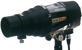
'Snoot' or 'spot adapter' |
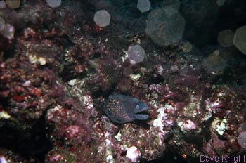
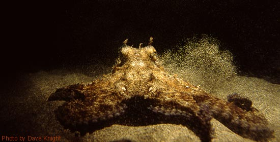
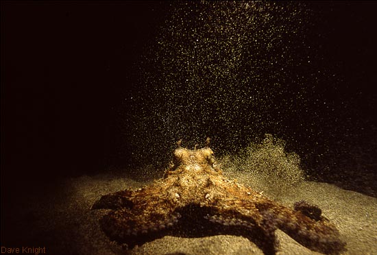 NARROW
BEAM:
Top lighting with reduced beam-angle helps to overcome poor visibility.
Here there is no ambient light because the photograph was taken at
night. The SLR housing was placed on the sand in front of the octopus
and the flash unit was held by hand. The light cone from the flash can
be seen clearly because there is a great deal of suspended matter.
Below shows the same photograph after cropping and retouching.
NARROW
BEAM:
Top lighting with reduced beam-angle helps to overcome poor visibility.
Here there is no ambient light because the photograph was taken at
night. The SLR housing was placed on the sand in front of the octopus
and the flash unit was held by hand. The light cone from the flash can
be seen clearly because there is a great deal of suspended matter.
Below shows the same photograph after cropping and retouching.
Macro
photography
For macro photography, the same compromise between top-lighting and
forward lighting as is used for general photography is appropriate,
except that the flash unit should be placed close to the subject. The
reason for the proximity is that the lens should be used at small
aperture (large f-number) in order to give good depth of field, and the
light must be correspondingly bright. It may be necessary to switch to
manual exposure mode in order to force the camera to use a small
aperture, especially when using a compact camera with an external macro
lens (an auto only camera is not ideal). In the absence of a TTL flash
system, exposure is easily controlled by moving the light source closer
to or further away from the subject, or by varying the light output. |
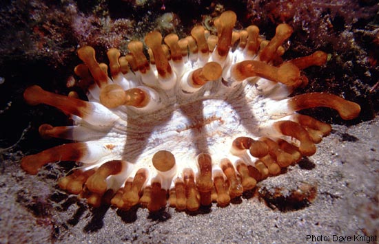
 |
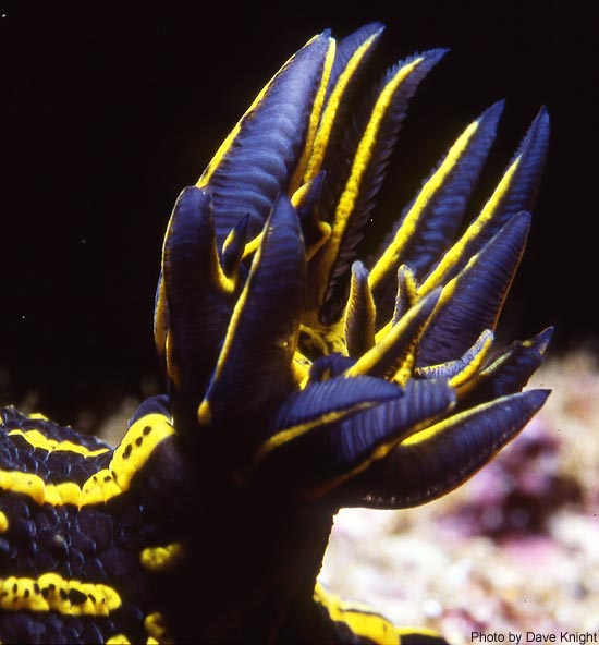 HIGH
CONTRAST: Macro photograph with top lighting (gills of
nudibranch Hypselodoris elegans, about 20 mm across.
50 mm macro lens at f/22).
HIGH
CONTRAST: Macro photograph with top lighting (gills of
nudibranch Hypselodoris elegans, about 20 mm across.
50 mm macro lens at f/22).
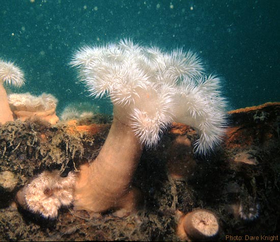
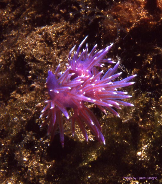 LOW
CONTRAST:
Macro photograph with the flash unit above and to the right, pointing
at about 45° to the lens axis to make light penetrate between
the
spines of the two mating nudibranchs.
LOW
CONTRAST:
Macro photograph with the flash unit above and to the right, pointing
at about 45° to the lens axis to make light penetrate between
the
spines of the two mating nudibranchs.
| A fully articulated lighting arm allows a variety of
lighting
positions suitable for macro photography, but can be cumbersome if
macro photography is to be the principal activity. A more compact
arrangement is possible if the camera housing has an accessory shoe or
some other arm base directly above the lens; a short arm fixed directly
to the housing being known as a 'macro mount'. A macro mount generally
enforces a lighting direction intermediate between top and forward, and
is suitable for the majority of macro photographs. If the enforced
direction should prove to be unsuitable, an accessory shoe fitting can
be released simply by loosening a knurled locking nut. Macro mounts are
available in various lengths (and can be made up from arm components),
and when reasonably long are also suitable for general-purpose forward
lighting in conditions of fair to good visibility. |
MACRO MOUNT |
Dual flash
Some photographers prefer to use a dual flash system. Some points on
this subject worth noting are as follows:
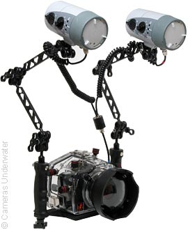
ikelite SLR housing with dual TTL flash |
One flash
tends to fill-in the shadows left by the other. This means
that shadow regions are better illuminated than when using a single
flash, and the resulting photographs are generally improved.
Dual flash
can produce very odd-looking shadows, especially when used
at short range. Use of diffusers is advisable in most circumstances,
and both flash units still need to be angled judiciously for best
effect.
If both
flash units are aimed at the same point, the level of
illumination is doubled (assuming that both give the same output). With
all other variables held constant, users of dual flash can work at
smaller apertures than users of single flash and thereby achieve
greater depth of field. |
If
both flash units are aimed at different points, the field of
illumination is increased. Given that most cameras have a rectangular
format, spreading the light into an oval pattern can help to reduce the
fall-off of light intensity that sometimes occurs at the edges of the
field when using wide-angle lenses.
Experimentation
While it is important to be familiar with basic lighting technique and
the reasoning behind it, it is not always necessary to adhere to it.
There is often considerable merit in unusual positioning of lights or
in unusual lighting directions. With this in mind, note that the
diver's safety partner (buddy) can be employed to hold a flash unit much further from
the camera than can be achieved by the photographer alone. Some
manufacturers (e.g., ikelite) make flash extension cables, one of
which, for example, can be used to fire a flash unit placed within a
compartment of a shipwreck while the camera looks in from outside.
Separate slave flash units can also be placed at some distance from the
camera, to be triggered when the flash attached to the camera is fired.
Note that underwater tripods are just as useful for mounting lights as
they are for mounting cameras.

© D.
W Knight, July 2006 - Oct 2006. Updated Aug. 2011 & Feb. 2018.
David Knight asserts the right to be recognised as the author of this
work.