 |
Dome port theory
by David Knight
Finding the focal point of a dome port
The focal point of a lens is the point at which light from an object at infinite distance is made to converge. Since an underwater dome port is a diverging lens, the focal length is strictly negative (the image is virtual), but we will treat it as a positive quantity here because the intention is to derive an expression that can be used to estimate the distance from the camera to the virtual image.
In standard UW photographic practice with lenses of moderate to wide field of view (FOV), an attempt is made to place the lens entrance pupil at the centre of curvature of the dome. This choice ensures that rays normal to the dome surface are undeflected on their path to the lens, thereby making the FOV underwater the same as it is in air. Note however that pupil positioning is rarely accurate when using an interchangeable lens camera, being dependent on generally limited choices for port extension length, and being subject to the fact that the camera is always mounted (inside the housing) in the same place, regardless of which lens is in use. Thus, although we must assume that the lens is in the right place for the purposes of theory, it is important to be aware that incorrect positioning will introduce error in practice.
Thin dome approximation
In the diagram below, the entrance pupil of a camera lens is placed at the centre of curvarure C of an air-filled thin-walled dome of radius r that is immersed in water. A ray travelling along the lens axis is undeflected and goes straight to the camera, but an off axis ray is deflected through an angle φ. Thus rays from infinity appear to come from a point F (the secondary focus). If the camera lens is to be able to focus on the virtual image at F, it must have a minimum focusing distance of ≤ s + b (where b is the back-focal distance).
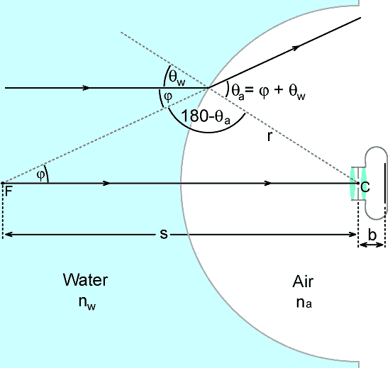
Using the Sine rule:
s / Sin(180-θa) = r / Sinφ
but Sin(180-θ) = Sinθ
Therefore
s / Sinθa = r / Sinφ
In the small angle limit, Sinθ → θ , therefore
s = r θa / φ
but, by inspection, φ = θa - θw , hence:
s = r θa / ( θa - θw )
Factoring θa from the denominator and cancelling gives:
s = r / ( 1 - θw / θa ) . . . . . . . . (1)
By Snell's law of refraction:
nw Sinθw = na Sinθa
(where nw and na are the refractive indeces of water and air). In the small angle limit this becomes:
θw / θa = na / nw
substituting this into (1) gives:
| s = r / (1 - na/nw ) |
If we use the approximations na = 1 and nw = 4/3, then 1-na/nw = ¼, and
| s = 4r |
Thus, for a thin dome immersed in water, the virtual image of an object at infinity appears at a distance of about 4 radii from the centre of curvature. On the somewhat unreliable assumption that the lens pupil is correctly placed at the centre of curvature; adding 4r to the back focal distance b (which can be obtained from the lens data or estimated by noting the apparent position of the iris) gives an upper-limit estimate of the required minimum focusing distance for the camera lens.
In practice, the use of very thin domes is not possible in pressure-resistant underwater housings. If the dome has finite thickness, and is made of material having a refractive index greater than that of water (such as glass or acrylic), then the virtual image will be moved slightly closer to the camera. Thus the minimum focusing requirement is a little more severe than the simple 4r rule would seem to imply.
Thick-walled dome-port formula
The derivation of the focal distance for the general case is somewhat more tricky than the thin-wall approximation, but we can start by analysing the passage of a light ray striking the port at an arbitrary angle.
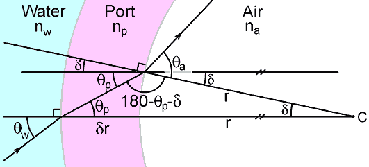
In the diagram above, an incident ray (in water) meets the port surface at an angle θw to the perpendicular and emerges into the port material at an angle θp. The relationship between the two angles is given by Snell's law in the small-angle limit:
nw θw = np θp . . . . . . . . . . . . . . . (2)
As the ray traverses the port to strike the inner surface, the normal to the surface undergoes an angular displacement δ . Hence the angle of incidence at the inner surface is θp + δ. If the ray exits the port material into the air at an angle θa , then Snell's law gives:
np ( θp + δ ) = na θa . . . . . . . . . . (3)
By inspection of the diagram; using the Sine rule we get:
Sin(180 - θp - δ) / ( r + δr) = Sinθp / r
Where r is the dome inner radius, and δr is the dome thickness. Now, since
Sin(180-θ) = Sinθ , in the small angle limit this becomes:
(θp + δ) / (r + δr) = θp / r
Rearrangement gives:
δ = θp δr / r . . . . . . . . . . . . . . . . . (4)
Substituting this into (3) gives:
np θp (1 + δr / r ) = na θa
and using (2) to substitute for θp gives:
θw / θa = (na / nw) / (1 + δr / r) . . . . (5)
As shown below, an expression for the focal distance s is obtained in the same way as for the thin-walled case:
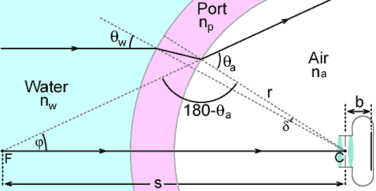
Referring to the diagram above, using the Sine rule gives:
s / Sin(180 - θa) = r / Sinφ
but Sin(180 - θ) = Sinθ , and so, in the small angle limit:
s / θa = r / φ . . . . . . . . . . . . . (6)
A problem that remains however, is that of eliminating φ so that s can be expressed in terms of fixed physical parameters. The solution is obtained by drawing parallels, as shown in the diagram below:
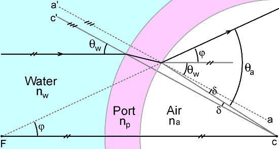
by drawing a line a - a' parallel to the line c - c' against which θw is defined, we can see that:
θa = φ + θw + δ
i.e.,
φ = θa - θw - δ
Using this in (6) gives:
s = r θa / (θa - θw - δ)
Substituting for δ using (4) gives:
s = r θa / (θa - θw - θp δr / r)
and substituting for θp using (2) gives:
s = r θa / [ θa - θw - θw (nw / np) δr / r ]
i.e.,
s = r θa / [ θa - θw { 1 + (nw / np) δr / r } ]
Factoring out θa from the denoninator and cancelling gives:
s = r / [ 1 - (θw / θa) { 1 + (nw / np) δr / r } ]
and substituting for θw / θa using (5) puts the focal distance in terms of fixed system parameters and solves the problem:
| s = r / [1 - (na / nw) {1 + (nw / np) δr /r } / (1 + δr / r) ] |
Example calculations
Some example calculations are shown below. Accurate data were available for the ikelite 6" port, but the thicknesses of the boron crown-glass (BK7) ports are guesses. Still, the calculations give the general idea, which is that the finite thickness of the port puts the virtual image some 10 to 15mm closer to the camera than the simple 4r rule would suggest.
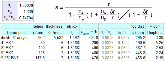
The infinity correction figure, in diopters, is simply the reciprocal of s in metres, i.e., it is the magnifying power required to make rays from the virtual image become parallel if the correcting lens is placed at the centre of curvature of the dome.
 Don't
forget to add the back focal distance b when estimating the minimum
focusing distance requirement. The position of the focal
plane in
an interchangeable lens camera is often marked with the symbol
  .
The position of the lens entrance pupil should be given in
the
data sheet, but it can also be estimated by stopping-down and noting
the apparent position of the iris.
.
The position of the lens entrance pupil should be given in
the
data sheet, but it can also be estimated by stopping-down and noting
the apparent position of the iris.You can download the open document spreadsheet used for the calculations above and play with the numbers for yourself → Dome port calculation spreadsheet dp_calcs.ods (right click , 'save target as' ). You will need Open Office to open the file.
An alternative approach to the dome port formula is given here:
Secondary focal point of a dome port
© David Knight 2012. Updated Feb. 2018.
David W Knight asserts the right to be recognised as the author of this work.