 _ _ |
 _Demodulators
and signal rectifiers _Demodulators
and signal rectifiers |
AM Precision audio detector
Patrick Turner, of Turner Audio (Australia) has made considerable improvements to the original comp. follower detector circuit. The following has been abstracted from e-mail correspondence (19th Nov. 2015 - 24th Nov. 2015) with Patrick's permission. Note that this information relates to an experimental project in progress, the aim of which is to reduce THD in the envelope of of an AM signal by using a precision detector for NFB. The reason for doing so is that passive modulators are not as linear as is widely believed. More information is expected to appear on the Turner Audio website.
DWK
" I built a version of your idea for AM detector using a discrete bjt op-amp, where I could take audio output from two collector load resistors between collectors and +/- rails. I'm making an AM modulator, and want to detect the raw AM wave to give a NFB signal that is applied to a diff. pair with input signal to other side. The output from one side of the pair is to the AM modulator, and the NFB removes the several % of envelope shape THD. This idea is old. HP used it with tubes in the ancient 1960s HP606A; good for 50 kHz to 65 MHz carrier, and quite a wide AF bandwidth for the 0.5 MHz to 1.7 MHz AM band. So far, my op amp will allow 5 MHz of carrier, while your original schematic I found did 1.7 MHz when I built it here. Probably, I could have used better / faster bjts for the discrete op-amp, but I don't know what type numbers to choose.
The circuit I built first to test the idea is:
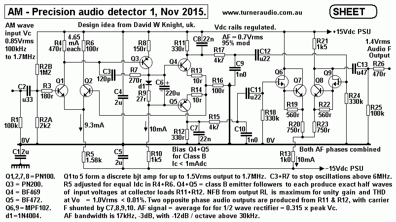
Notice I have quite high currents and low RLs for all bjts, but this gave reasonable detection to 1.7 MHz.
Higher Ic = higher bjt gm = higher voltage gain.
Then I decided to use my favourite discrete op-amp with symmetrical PNP & NPN devices all the way to the output.......
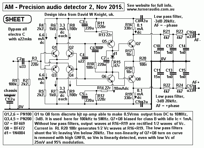
I found that a 0.5 V rms un-modulated carrier was -3 dB down at 10 MHz, a fair result from parts bought at a suburban Jaycar store for obsessive hobbyists. In other words, the op-amp is a linear follower with pole at 10 MHz, but you can have only 0.5 V rms. So when you have 100% mod, you have 1 V rms at R20 and the pole moves down to 5 MHz. But at 100 kHz, then there's a lot more output available at R20 100 Ω. Higher values for R16 and R19 than 330 Ω means that the peak swing away from the rails can become too much....
But this works better than all the IC op-amps I've been able to buy easily. PN100 is a generic replacement for 2N2222, and I've found it quite a good bjt. BF470 and BF472 are "video bjts" which I saw in a 1982 audio amp schematic by David Tilbrook. Just how much faster it could it go with better bjts is not known.
Both the above schematics circuits require R&C critical damping at HF to prevent oscillations above 6 MHz (see C6, 100 pF, plus R6, 100 Ω, to shelve the HF gain). Connection of a small amount of C across output RL R20, say 150 pF, does cause some oscillations. So success relies on using only R to load the amp, C causes extra phase shift as f rises, so it oscilates.
But the output for AF is NOT within the GNFB loop; this is the real benefit: no diode and C across R20. The output is from a collector current source, not a voltage source enforced by FB, so that the AF circuit looks like say 20 k feeding 330 Ω, and if each rectified ½-wave was 1 V pk, then average V dc out = 0.315 V dc if capacitance across the 330 Ω is large enough to shunt all of the ac.
The shunting of collector loads does not upset bjt function. If C shunts RF, but not AF, then the C would reduce Miller capacitance to the base inputs. The peak to peak max for AF would be 0.315 V, so max V AF is 0.157 × peak half wave V ac. This type of detection doesn't involve diode charging and discharge, so no time constants to worry about causing slew dn. Its not as efficient as diode detection, but it seems to work just fine. The value of R20 100 Ω seems high, but you don't want R20 too low, and its peak current is applied to 330 Ω so you get 3.3 × peak V dc in 330 Ω, thus compensating for ineffiencies. I like headroom, hence the use of ±15V supplies. Using just +12 V dc will work, but gives lower max Vo, or, put another way, higher rails give more Vo with low THD, or the same as for 12 V rail, with lower THD.
The use of symetrical input pair goes back 30 years to innovative audio circuitry, with NPN and PNP diff. pairs working in parallel, and a gain stage with PNP & NPN bjts in series - so no R loads, so huge gain, and this is a good driver for a mosfet amp. Many things are more complex that what I came up with. My pages on power amps (solid state) tell the story of the 2 × 300W amp I made in 1996. I was inspired by Douglas Self and others who wrote in Electronics World.
But the op-amp I made here can only make 0.5 V rms at 10 MHz. At 1 kHz, it can do far more, but the higher the Vo, the greater are the internal gymnastics to keep the output voltage linear to input, because like all DD devices, they slow down with f increase.
I built one good Vac analog meter, OK for Vac 5 Hz to 250 kHz at least, 1 mV to 300 V ac, in 11 ranges 10 dB appart. It's good, and I built another, with 3 Hz to 300 V ac, but up to 6 MHz, with the faster discrete op-amps. The secret was to use a bridge rectifier with Ge diodes or IN5711 Schottky in the NFB loop, so Vdc to drive meter is linear to the RMS signal current in NFB path. I am not sure if the principle could be used to produce demodulated AM - maybe.
Maybe 60 years ago, in 1955, Selsted & Smith came up with an "infinite impedance" AM detector for which they made lots of claims (its in the rear end of the RDH4 - Radiotron Designers Handbook, 4th edition). I tried it, using tubes of course, but it's not as hot as they said.
I then invented a detector using a 12AU7 cathode follower to buffer the last IFT output, then a diode to 270 pF, with 1 MΩ to -50 V dc, then 100 kΩ + 50 pF LPF, and then a second CF to buffer the detected audio signal (see Radio re-engineering, - Other misc. AM radio schematics). Well, this is simple, and I've done it with darlington connected bjt followers, and it's all good, but there's a flat spot on the AF at more than 95% mod, because of diode drop. Ge works well, with Schottky maye better (IN5711), but I could easily get up to about 10 V rms AF with THD < 1% at 90% mod. This detector is far better than in every accountant designed AM radio I had brought to me for singing lessons. It also beats everything in RDH4. However, at carrier Vc < 0.5 V rms, some THD creeps in when mod % is high. But I didn't want good long distance AM reception, and with strong locals the AVC network keeps the carrier and hence AF quite high with low THD.
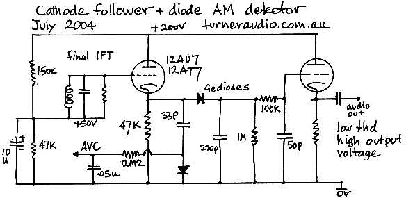
Notice the R added across the last IFT LC, this is usually 100 kΩ to slightly reduce Q so extending IFT bandwidth and hence AF bandwidth. The use of what is a virtual CCS to discharge 270 pF does allow condsiderable RF ripple without causing THD. The 1 MΩ gives idle 0.05 mA dc through the diode, so it's permanently slightly 'on', so the forward V drop is reduced and RF ripple voltage is fairly constant for the AF voltage produced. Low diode self C is a must, so maybe IN5711 is better than Ge.
I've used this circuit to detect AF after the output stage of an RF gene I made with a 12AU7oscillator and a 6BX6 output tube. Such simple cathode modulated pentodes have typical envelope THD of 7% at 90% modulation.
So the use of triode diff amp with - you guessed - 12AU7 gave open loop differential gain of about 13, and envelope THD is reduced by 15 dB at all mod levels, so I am not left guessing when I ask "is the receiver making the THD, or is it my sig gene?"
It all falls apart for 100% mod if the AF is over 5 kHz, but then if you get 5 kHz right, and then use 50% mod, it goes to 20 kHz AF quite well, and the AF response of the receiver can be properly measured. IFTs in tube sets need serious tweaking to extend usual BW from 7 kHz, (3.5 kHz audio) to say 10 kHz, with the same skirt selectivity. In bjt superhet tuners, with two IFTs, there is only one high Q LC network. So AF is limited to 1.5 kHz; and boosting the treble does nothing because there is no treble to boost.
Anyway, in my tube modulator, some trial and error was needed to stop parasitics, but it's a lot simpler than the HP606A which somebody gave me....
The HP 606A is a fully tubed RF gene for 50 kHz to 65 MHz in 6 switched bands, in box about 45 cm wide, 33 cm high and 33 cm deep . Internally, it is a masterpeice of high quality electro-mechanical craftsmanship, knocked up by guys who'd probably had to make all sorts of gear to win WW2. 2× 6CL6 are used for a push-pull RF amp with tuned anode tank. LCs for different bands are on a large rotating turret switch, and there's no sign of compromises by accountants. A 6B4 is used to cathode modulate the 6CL6s, and the 6B4 grid signal comes from a triode pentode diff. amp using a 6AW8, with AF in to the triode side and detected AF to the pentode side. THD is <1% at 97% envelope - quite good for 1958.
The internally detected AF is from a sec. winding on the anode LC tanks, which give max 3.0 V rms carrier output with 50 Ω in series. But additional sec. turns give 6 V rms to feed 2 series Ge diodes feeding a R&C network - a very crude detector, but it works.
I analyzed and found that about 15 dB to 20 dB of NFB is used. One reason for stability is the tuned LC anode tank; it excludes both LF and HF parasitics, which can happen with untuned circuits within thre NFB loop. Full circuit details are in the HP606A Operation and Service Manual.
I don't know what is done nowdays with AM transmissions; but here the ABC here puts out a splendid signal with 9 kHz AF, and it sounds better than my FM tuner full of ICs I use to get FM in the kitchen, using an AM radio AF amp. This is all despite networking where a programme in Sydney goes to a satellite encoded by digits and VHF and then back down to a whole lot of stations for re-broadcasting by remaining Steam Powered AM Transmitters, SS FM transmitters, or to digital radio, or to the Internet for pod-casting etc.. At one time, they used to receive AM transmitted from Sydney in "special quality" receivers in Melbourne, over 1,100 km away, then re-transmit it. The quality was good enough not to fetch complaints. Just what those special receivers were is a mystery, but I heard AWA was involved, and they kept stuff like that secret.
My cathode follower detector really needs to make at least 2 V rms of AF average to avoid THD caused by diode drop and CF losses.
The detector of yours does a good detect job even with Fc at 25mV, and 100% mod. This better suits my present purpose to make a wide band AM modulator without any tuned circuits, although I have used hand wound RF toroid chokes of about 20 mH with CT, and shunted at modulator with low value RL to flatten response to as wide as possible. I don't know if I can get away without a tuned LC because initial tests with a passive detector gave all sorts of parasitics.
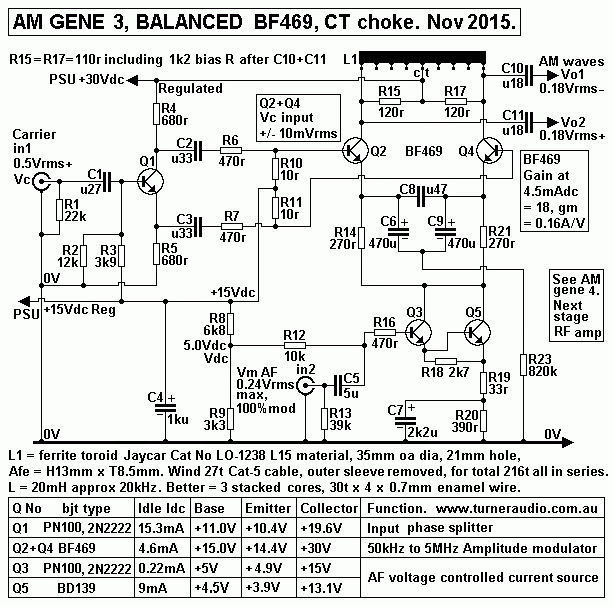
I finally got my long tail modulator with 2 × BF469 to give 100 kHz to about 5 MHz of flat bandwidth, with 33 Ω across each half of the15 mH L with CT. I have an amp. with gain of ×12 following, and I get two phases of 0.5 V rms and at Vc 200 kHz, THD in +/- envelopes is 2.5% at 95% mod without any NFB loop. The THD is < 1% at 50% mod. At 2 MHz, with bjts beginning to struggle with f, the THD = 5% at same levels, so at 4 MHz I expect more THD.
The detector worked fine, up to 2 MHz at least, and then I tried using detected AF as NFB signal with simple long tail pair with gain of 10. However: each and every attempt to apply more than 3 dB NFB gave dismal results with parasitics popping up in many different ways, and I can say that this path to a working linear modulator, ( THD <1% at 95%, for all f ) not going to work, because the modulator does not have tuned circuits so it can easily oscillate.
The detector does have a high amount of carrier harmonics which need reduction, much more HF harmonics than you get with simple old diode+C+R. So any LPF filter, even with pole at 50 kHz, with high slope seems to create a path for low level carrier harmonics to cause mayhem, and for phenomena such as oscillating at 10 kHz with no external mod signal applied, above some low threshold of level, far lower than wanted, and fiddling with time constants does not seem to help. Like all cascaded circuits including lots of stages with gain and GNFB, things that you hope won't oscillate just will oscillate, at whatever f is possible if there's just enough phase shift.
AND, after getting it to work slightly with only a useless 3 dB GNFB, using a 1 kHz square wave gives horrid amounts of ringing and distortions.
So I'll have to settle for a the passive modulator which is actually better over all than another tubed modulator I made with NFB in 1995.....
The HP606A RF gene is so much simpler, and with tuned anode tanks there's no chance of stray f away from fo ever showing up in anode circuit, which can only work at the tuned f. So much for trying to get away from radio tuning gangs. I've spent days trying with this thing, and have about 5 times the number of parts used compared to HP606A, which does 50 kHz to 65 MHz, 6 ranges, nicely calibrated, full 97% mod with envelope THD quite hard to see; it is a brilliant simple thing from the past......
Regarding digital methods: almost nobody online has published anything useful about really linear modulators. Probably, there is a function generator chip that does it better. I once had a Topward, very fragile, but that did a good AM wave, and it was broad band, so you could AM modulate 100 Hz with 5 Hz.
PT
27th Nov. 2015.
| _ |
_Demodulators
and signal rectifiers |
