All Mode Transmit, Receive and Digital Readout Adapter for
the RA17.
By D. W. Knight.
Version: 1.00 (Unicode)
Part 2.
Working Specification:
A simplified block diagram of the RA17 transceiver adapter
under consideration is shown below:
The diagram shows all of the important analogue signal
pathways , but does not show function switching and transmit-receive
(T-R) switching arrangements explicitly except where essential
to the signal flow.
Basic Adapter Architecture:
The adapter receive-side architecture is similar to that of the
author's earlier adapter and should be largely self-explanatory.
It is assumed that receiver muting (or desensitisation) on transmit
will be controlled by the final amplifier T-R switching system,
and so the only T-R switching required in the adapter receive-side
circuitry is the insertion of a 'monitor level' pot in the audio
signal path. The product detector is fed from the synthesised
carrier generator used by the transmitter, or from a variable
CIO (ie., BFO), according to function control switching described
later. A side-tone detector is provided so that the difference
between the carrier and the BFO can be heard in the loudspeaker
when sending CW. RIT is provided by switching a variable capacitor
across the LF VFO input as necessary
Additional functionality not shown on the diagram, but nevertheless
desirable, is as follows:
1) An audio notch filter for the removal of unwanted beat notes.
2) All mode squelch, for silent channel monitoring. This requires
an AGC (AVC) input from the main receiver, which may also be used
for receiver muting during transmission. The RA17 AGC range is
0 to -25V, high impedance. 0V corresponds to maximum gain, but
a quiet channel typically gives about -2V. Very strong stations
give an AGC voltage of -16 to -18V. The AGC line can be connected
to a FET op-amp voltage follower operating between 0 and -30V
supply rails, and thence to an adjustable threshold detector.
One caveat however, is that something needs to be done about the
appalling AGC characteristics of the RA17, particularly to give
a fast attack and a slow decay optimal for SSB reception.
3) Additional IF filtering to improve SSB reception in crowded
band conditions.
4) CTCSS
The transmit-side architecture is an implementation of the 'N+3'
translation scheme outlined earlier. The HF VFO signal from the
RA17 is counted and processed digitally to produce latched BCD
data representing the 'Megacycles' setting 'N'. For simplex working,
this is fed through to the 'N+3' synthesiser module, where it
programs a divider in a loop which locks a VCO to the 1MHz system
reference. For duplex working, the N+3 synthesiser obtains its
MHz data from a pair of BCD coded thumbwheel switches. In LF mode,
the MHz data are ignored, and the synthesiser outputs 2MHz. No
arrangements are provided for duplex working in LF mode, it being
assumed that the exciter will be used as a signal generator rather
than as a transmitter below 1MHz.
In the transmitter signal path, audio signals are first brought
up to line level and applied to a VCA. A loop-out patch is provided
prior to the VCA for any additional audio processing (eg., compression)
which may be required. In SSB modes, the ALC voltage is obtained
from the RF output in order to maintain overall linear operation
of the RF amplifier chain. The RF level is normally sampled at
the 2nd mixer output, but can be sampled at the interpolation
transmitter output when a converter is in use. In FM mode, the
RF amplifier chain is biased in class C, and the ALC voltage is
obtained locally by rectifying part of the VCA audio output. SSB
is generated by using a symmetric linear-phase filter centred
on 100KHz and side-stepping the carrier by ±1.8KHz. Recall
that the USB and LSB carrier frequency designations need to be
swapped on changing between 'N+3' and 'N-2' translation schemes
(ie., on switching between Wadley and LF, or as requested by a
converter). The carrier generator is a VCO locked to a 200Hz signal
derived by dividing the 1MHz system reference by 5000. The required
carrier frequencies (98.2, 100, or 101.8 KHz) are obtained by
setting the loop programmable-divider to 491, 500, or 509 as necessary.
For FM, audio is injected into the VCO control terminal, the loop
response cut-off being below the lowest required modulating frequency
so as not to thwart the modulation process.
In the translation from 100KHz to the interpolation transmitter
frequency, provision is made for two LF VFO inputs. This allows
for split-frequency CW DX working outside the range of the RIT,
and if the interpolation TX is used to drive a VHF or UHF converter,
permits use of repeaters. If an auxiliary VFO is in use, the counter
must switch between input sources on going from receive to transmit.
The frequency counter samples the LF VFO signal and applies suitable
offsets to obtain the KHz part of the operating frequency. In
addition, it accepts MHz data (from an appropriate source) for
parallel loading into the display register, and corrects the MHz
reading in the event of over or under-range operation of the interpolation
receiver or transmitter. Since the register used to perform the
correction is effectively an extension to the counting register,
the counter can be switched to perform as a normal DFM with minimal
added complexity. Using 74F series logic in the fastest part of
the counting chain will give a typical maximum input frequency
of 125MHz. Use of a ÷10 prescaler (and increasing the sampling
time from 100ms to 1s) will extend the maximum input frequency
to about 1250MHz.
RA117 Issues: For those wishing to modify the adapter architecture
for use with the RA117, there are some important caveats. The
major point to note is that the 2nd VFO output of the RA117 is
buffered, and the simple fine-tuning and RIT scheme proposed above
will not work. RIT is essential, and so a solution would be to
generate the 1.7MHz heterodyning signal in the adapter and feed
it out to the RA117. In this case, the 1.7 MHz signal can be fixed
on transmit (possibly by ÷10 ×17 synthesis from the
1MHz ref.) and obtained from a VFO on RIT receive. All of the
considerations which follow can be re-worked for the RA117 (and
will have to be). Note particularly that the required LF VFO and
auto-tuning counter offsets are completely different, and the
USB and LSB carrier assignments are always the reverse of anything
which applies to the RA17.
2 - 3MHz Interpolation Transmitter Auto-Tuning:
In order to produce transmitter signal on the interpolation intermediate
frequency (ready for N+3 MHz translation onto the output frequency)
it is necessary to filter the first TX mixer output to select
the required component (3-Δf) from the image component (3.2-Δf)
and any remnant of the VFO signal (3.1-Δf). In traditional
transceiver designs, this is done by having at least one extra
gang on the interpolation tuning capacitor, but this option is
unfortunately unavailable. The simplest (and least ergonomic)
solution to this problem, is to provide a manual tuning dial;
but given the low carrier frequency (100KHz), this carries the
serious risk of accidental radiation on unwanted frequencies and
is therefore technically unacceptable. The block diagram instead
shows an 'auto tuning' module, which somehow senses the VFO frequency
and tunes the bandpass filter appropriately. The most obvious
approach would be to obtain a binary representation of the VFO
frequency, and apply it to a 10 or 12 bit D-A converter to provide
a DC reference for a motor-servo driving a tuning capacitor. A
small amount of curve (gamma) correction will be required to account
for the square-law relationship between tuning capacitance and
frequency. To reduce unnecessary wear on the system (and avoid
whirring noises while tuning the wireless), the servo should be
allowed to operate only in transmit mode, or upon pressing a 'pre-tune'
button. A purely electrical tuning method would, of course, be
preferable, and the author is open to suggestions on this matter.
One might, for example, consider using high-capacitance varicap
diode tuning, but contra-indications for varicaps are low Q, thermal
drift, and varactor effects producing parasitic signals.
The frequency counting system produces BCD data representing the
offset LF VFO frequency, and it is natural to consider using this
to tune the '3-Δf' BPF. Such a choice is complicated however,
by the need to perform a BCD to binary conversion, and by the
fact that the transmitter must work normally when the counter
is switched to read an external input. The auto tuning system
should therefore be provided with its own binary counter, data
latch, and housekeeping logic, a choice which additionally allows
that any auxiliary VFO can be sampled independently of the main
VFO. Note that on switching from receive to transmit in RIT mode
(or pressing 'pre-tune'), a delay of at least one counter cycle
(125ms) is required before activating the auto tuning system,
to ensure that the counting register contents represent the transmitter
VFO setting.
When tuning the interpolation transmitter, it does not matter
which translation scheme is in use because the requirements are
the same in either case, ie., the output BPF is always tuned 100KHz
below the VFO frequency. Consequently, exotic counting schemes
and mode changes are unnecessary, and devising a counter is simply
a matter of choosing an appropriate offset to obtain contiguous
control-voltage steps. If the LF VFO counting gate period is chosen
to be 100ms (for 10Hz resolution), there will be 100 000 steps
between 2.1 and 3.1 MHz. The next highest 2^n is 131072 (ie.,
2^17); and if the required range is to be placed symmetrically
in the middle of this interval, the counting system must output
0 if the VFO is at 1.94464 MHz, and it must output the binary
equivalent of 131071 (ie., 1FFFF) if the VFO is at 3.25535 MHz.
The VFO of the author's RA17C18 was found to tune from 2.055 to
3.172 MHz (end-stop to end-stop). Other (100KHz IF) RA17 receivers
are likely to be similar, and so the VFO cannot reach the limits
of the counting range and there will be no ambiguities (an aux
VFO must of course be designed to observe these limits also).
The required offset is therefore that which will cause a modulo
131072 count register to contain 0 after 194464 pulses, ie.:
Offset = (131072 - 194464)mod 131072
= 131072 - (194464 - 131072)
= 131072 - 63392
= 67680
(check: 67680 + 194464 = 262144 = 2^18)
ie., the preset inputs to the count register should be hard-wired
to the binary equivalent of 67680;
ie., 1 0000 1000 0110 0000.
It takes 17 bits to represent a number up to 131071, and the values
of the places are as follows:
|
n |
16 |
15 |
14 |
13 |
12 |
11 |
10 |
9 |
8 |
7 |
6 |
5 |
4 |
3 |
2 |
1 |
0 |
|
2^n |
65536 |
32768 |
16384 |
8192 |
4096 |
2048 |
1024 |
512 |
256 |
128 |
64 |
32 |
16 |
8 |
4 |
2 |
1 |
If the highest 12 bits of the register are latched and applied
to a DAC, the DAC output will change every 320Hz. The BPF to be
tuned can be expected to have a 3dB bandwidth of about ±10KHz
at 2MHz; and so 320Hz resolution is more than adequate. If a 10-bit
DAC is used, the resolution will be 1.28KHz; which is marginal
in view of the fact that any mechanical servo must have a dead-band
to prevent it from hunting. The positional feedback system of
the servo must, of course, have a resolution of greater than 212
(4096) steps for a 12 bit comparison, and 210 (1024)
steps for a 10-bit comparison.
TX Output Tuning:
As mentioned previously, a filter is required at the TX output
to select the wanted 'N+Δf' component from the unwanted
'N+6-Δf' component (ie., there is a strong unwanted signal
4 - 6 MHz above the wanted signal). How this selection is accomplished
will depend on the final amplifier configuration. If the output
is used to feed the driver and PA of a valve transmitter, the
existing driver and PA tuning controls may prove sufficient to
make the selection, and the output can be left dirty. If a wideband
transistor PA is used, a much more elaborate arrangement will
be necessary, and it may be sensible to build the PA into the
adapter.
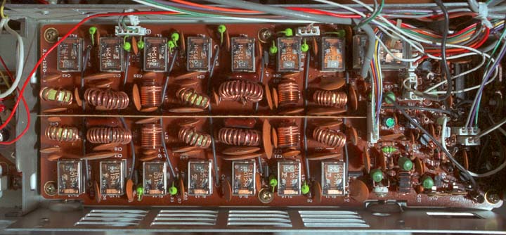
Low-pass filter section of the Kenwood TS430S
Transmitters using wideband transistor power amplifiers generally
use relay-switched low-pass filters to remove harmonics of the
output (see illustration above), and it requires at least eight
filters to cover the entire 1.6 - 30MHz HF spectrum properly.
These filters are usually controlled by band-switching or input
sensing circuitry; so in this case, they will have to be switched
according to the 'MHz' selection. In addition, the 'N+6-Δf'
signal must be prevented from reaching the PA. At low frequencies,
the unwanted signal can be removed by means of diode or relay-switched
low-pass filters in the PA feed. At higher frequencies, carefully
designed band-pass filters will be required. Alternatively, the
benefits of wideband operation can be abandoned, and the adapter
provided with an output band-selector switch and tuning knob.
Such 'conventional' output tuning can also be automated; eg.,
by relay or turret coil-switching, and motor-servo controlled
variable capacitors, but the mechanical arrangements are necessarily
elaborate. If the adapter is for amateur radio use (most other
uses require type approval in the UK, including CB), it may be
sensible to omit filters for frequencies which have not been allocated
to the amateur service. This will permit considerable simplification
of the tuning arrangements, and will help to prevent accidental
interference to other services.
The Amateur Bands below 30MHz are as follows:
|
UK |
International |
approx λ |
|
135.7 - 137.8 KHz |
|
2200m |
|
1.81 - 2 MHz |
1.8 - 2 MHz |
160m |
|
3.5 - 3.8 MHz |
3.5 - 4 MHz |
80m |
|
7- 7.1 MHz |
7 - 7.3 MHz |
40m |
|
10.1 - 10.15 MHz |
10.1 - 10.15 MHz |
30m |
|
14 - 14.35 MHz |
14 - 14.35 MHz |
20m |
|
18.068 - 18.168 MHz |
18.068 - 18.168 MHz |
17m |
|
21 - 21.45 MHz |
21 - 21.45 MHz |
15m |
|
24.89 - 24.99 MHz |
24.89 - 24.99 MHz |
12m |
|
28 - 29.7 MHz |
28 - 29.7 MHz |
10m |
If a decision is made to provide an output band-selector switch
and restrict operation to HF amateur bands only, it may be sufficient
to control the N+3 synthesiser from the band selector knob. The
required ranges then will be 1, 3, 7, 10, 14, 18, 21, 24, 28,
and 29 MHz (total 10), which can be implemented with a standard
12-way rotary switch. It is not the author's intention to design
the adapter in this way, because it does not constitute a fully-integrated
transceiver system; but provision for the arrangement is inherent
in the basic architecture.
Primary System modes:
The principal function changing mechanism is the main mode switch,
which programs or activates the various internal modules according
to the front-end in use (Wadley, LF adapter, or Converter) and
status of the T-R switching system. The proposed primary system
modes are as follows:
Auxiliary: Although none of the demodulators is in use,
the digital frequency readout shows the RA17 channel centre frequency
appropriate to the front-end currently selected. Note that in
this design, the CW audio filter is made available to the auxiliary
AF input, this being useful if (say) the input is connected to
the AF line output of a VHF transceiver. RF Output is disabled
in transmit mode, but the microphone amplifier is active so that
a line output from it can be used to modulate another transmitter.
The Automatic Level Control (ALC) voltage (as for FM) is obtained
locally by rectifying part of the audio output. The Morse key
and Press-To-Talk (PTT) contacts are looped out to sockets on
the back panel, so that they may be used to key another transmitter.
NBFM: The carrier generator is set to 100KHz and left running
if the adapter is in standby mode (see later). In transmit mode,
the amplified microphone signal is used to frequency modulate
the carrier generator. Localised ALC is used because transmitter
drive level is not related to modulation depth.
AM: In this context, 'AM' should be taken to mean full-carrier
DSB, and the position is intended primarily for reception of broadcast
stations. In transmit mode, the RF output is an unmodulated carrier
on the channel centre frequency: This is done on the assumption
that anyone wanting to transmit AM will use high-level modulation
of the final amplifier (this RF output can, of course, also be
used for tuning-up). ALC is switched to 'local' (as for FM) so
that the modulation line output can be used to feed a high-level
modulator.
Channel Centred Carrier (Cent): In receive mode, this position
is primarily used for finding exact carrier frequencies by zero-beating.
In transmit mode, this position is used for tuning-up.
USB and LSB: In Wadley (or "N+3") mode, the carrier
oscillator is set to 98.2KHz for USB and 101.8KHz for LSB. In
LF (or "N-2") mode, the carrier is set to 101.8KHz for
USB and 98.2 KHz for LSB. Converters can select either of the
two possible assignments via a converter data input socket. Note
that the carrier frequencies have an exact relationship to the
1MHz system reference; which allows the use of static-offset counting
in the frequency readout system, and increases the refresh rate
and display stability in comparison to the author's previous adapter.
In transmit mode, the ALC voltage is obtained by rectifying part
of the RF output, the objective being to control the operating
point of the signal chain to achieve linear amplification. The
ALC system cannot be disabled, but a microphone volume control
is provided so that the operator can control the level of background
noise and the amount of compression used.
BFO / CW: When working simplex CW, one should ideally net
the transmitter zero-beat onto the remote station and then sidestep
the BFO to produce a satisfactory note for reception. The arrangement
shown allows a fast netting procedure, using a side-tone generated
by mixing the 100KHz carrier with the BFO. The BFO is first adjusted
so that the side-tone frequency falls at the centre of the CW
audio-filter response. If the receiver is tuned so that a remote
station's beat-note also falls at the audio-filter frequency,
transmission will automatically take place on a frequency which
is very close to that of the remote station. If a remote station
replying to a call produces a beat-note which does not fall in
the audio-filter band, it can be brought into the band by adjusting
the RIT control. Since the purpose of the BFO in this mode is
to produce an audible tone (rather than to measure frequency by
finding zero-beat), its deviation from channel centre is not subtracted
from the digital frequency display; ie., static-offset counting
is used and the readout shows channel centre frequency or transmit
frequency.
Variable CIO: When receiving, variable CIO mode is the
same as BFO mode, except that the BFO deviation is subtracted
from the frequency readout, ie., the display shows the zero-beat
frequency rather than the channel centre frequency. A pipelined
variable-offset counting scheme is used to maintain the same display
refresh rate as in the fixed-offset modes. This mode is intended
primarily for monitoring wide-band and non-standard SSB signals.
An associated transmission mode is probably not required.
External Features:
Some idea of a physical realisation of the adapter can be
had at this stage by noting the various controls and interfaces
which might be required. This is effectively a wish-list, for
controls including those which are useful but are normally ommitted
from commercial equipment due to cost or restricted panel space.
The point here, is to come up with a set of controls which are
reasonably self-explanatory to any moderately experienced radio
operator. Any functionality which cannot be used without reference
to a manual may be safely omitted on the basis that it will never
be used successfully (cf. VCR programmer). A possible solution
is as follows:
Front Panel:
Power on / off
Main mode switch: Rotary Switch. As described previously.
T-R Mode switch (RX, Standby, TX): Rotary switch. In 'RX'
mode, the unit will not transmit and the carrier generator is
turned off when not needed. In 'Standby' mode, the carrier generator
is kept running and transmission occurs when the PTT switch or
the Morse key is pressed. 'TX' mode permits 'hands-free' transmission.
In 'RX' mode, the Morse key may be looped out to a socket on the
back panel, so that it can be used to key another transceiver
without the need to move plugs.
Mic Input and PTT
Mic Volume
TX AF Input Select (Mic, Line, ...): Rotary switch.
TX Line Input Level: Screwdriver slot rotary pot.
Morse Key: Jack socket (may alternatively be placed on
back panel).
TX Output Tuning: Depends on configuration, discussed later.
BFO Tuning: Variable capacitor with reduction drive.
VFO Fine Tuning: Variable capacitor with reduction drive.
Transceiver Mode (Normal, RIT, Duplex KHz, Duplex MHz):
Rotary switch. Duplex KHz mode allows the TX interpolation mixer
to be fed from an external (aux) 2.1 - 3.1 MHz VFO or synthesiser.
The counter reads the RA17 VFO on receive, and the Aux VFO on
transmit. Defaults to RIT mode in the absence of Aux VFO drive.
Duplex MHz mode additionally allows the N+3 synthesiser to be
programmed via switches, independently of the RA17 Megacycles
setting (the adapter then works as a stand-alone transmitter).
MHz: Thumbwheel switch x2. Manual programming of N+3 synth.
in Duplex MHz mode.
Clarifier (RIT): Variable capacitor with reduction drive.
RIT Warning Lamp: LED. Lights in RIT or Duplex mode.
Pre-Tune: Push button, non-latching. Activates interpolation
TX auto-tuning system. Switches VFO to transmit frequency in RIT
mode (ie., momentarily disables RIT). Displays Aux. VFO KHz setting
in Duplex KHz mode. Displays switch selected MHz and aux VFO KHz
in Duplex MHz mode (ie., always displays the frequency on which
transmission will occur).
Squelch: Rotary Pot.
Side-tone Level: Rotary pot
Monitor Level: Rotary pot. RX AF gain in transmit mode.
Allows monitoring of modulation via receiver.
CW filter in / out
Audio notch filter in/out
Notch filter Tune: Rotary pot.
AF Gain
LS
Phones: 1/4" Jack socket.
Counter Mode (Normal, Ext. 125MHz, Ext. 1250MHz, BFO):
Rotary switch. 'Ext.' modes allows the counter to be used with
an external input, for general frequency measurement. The most
obvious use of 'Ext. 125MHz' mode is to check that the transmitter
has been tuned-up correctly (by attaching a short whip antenna
to the counter input), and so it is implied that the transmitter
continues to work normally except for the frequency readout. 'BFO'
mode sets the counter to read the BFO frequency (for setting up),
switches on the BFO (regardless of whether it is needed), and
enables side-tone injection. Side-tone allows the audible difference
between the BFO and the currently selected carrier frequency (98.2,
100, or 101.8 KHz) to be heard while the measurement is being
made, and incidentally provides a back-door method for measuring
the resonant frequency of the CW filter.
Ext. Counter input 0-125MHz: BNC. 50Ω (may alternatively
be placed on back panel).
Ext. Counter Input 30-1250MHz: BNC. 50Ω(may alternatively
be placed on back panel).
Digital Frequency Readout: 8½-Digit display, 10Hz
resolution.
MHz Tuning: LED Bargraph to assist tuning HF VFO.
Tuning Meter: Centre-zero MC meter. Indicates carrier position
in passband.
Level Meter: Standard MC meter: Indicates RF level in receive
mode (optional S-Meter if AGC line is available). In transmit
mode; indicates RF drive level when using SSB, and modulation
AF level otherwise. Indicates carrier level when the pre-tune
button is pressed in transmit mode (to assist in setting up).
Sys-Ref Error: LED to indicate when 1MHz ref. osc. is not
locked.
VCO Error: LED. Lights when Carrier and 'N+3' synthesisers
are out of lock. RF output is inhibited.
Under-range and Over-range: LEDs to indicate that
the interpolation receiver is operating outside the selected 1MHz
interval
Back Panel:
Mains Input: Filtered IEC.
Switched Mains out (optional): IEC Female.
Mains Fuse.
IF Input: SO239.
1MHz Ref. Input: BNC. High Impedance.
1MHz Ref. Out: BNC. Sine-wave output from the internal
Xtal osc.
LF VFO Input: BNC. High Impedance.
Aux. VFO Input (1.95 ≤ f ≤ 3.25 MHz): BNC.
Hi-Z. For split-frequency working. Electrically identical to normal
LF VFO input (except for lack of fine-tuning capacitors) to allow
use of VFO from 2nd RA17. Interpolation TX auto-tuning requirements
(discussed above) restrict the allowable input frequency range.
HF VFO Input: BNC. 50Ω input. Requires buffer amp
to be fitted in RA17. Wadley mode MHz readout is suppressed in
the absence of this signal.
LF Adapter Sense: Negative logic input (short to ground).
Converter Data: 25-way D. Converter type and parallel MHz
data input. T-R control output.
Aux AF Input: Phono.
RX AF Line Out: 2 x Phono.
RX Line out level adjust: Screwdriver slot rotary pot.
TX AF Line Input with T-R control: Multipole audio connector.
Primarily for data input
External TX audio processing in/out: multipole. For audio
processing (eg., compression) not provided by the adapter. Requires
link plug when not used. Can also be used as line in, replacing
mic amp etc. in adapter, for which reason should also be provided
with PTT contacts.
TX AF Line Out: Phono.
TX AF Line Out with PTT: Multipole Audio Connector.
TX AF line out level adj.: Screwdriver slot rotary pot.
Footswitch: ¼" Jack socket. Electrically the
same as the PTT switch input.
Morse Key Out: ¼" Jack. Loop-out to another
transceiver.
Interpolation RF out: BNC. For converters.
RF Out: BNC. To final Amplifier.
T-R Control: Output to control final amp, RX muting, antenna
switching, etc.
AGC Line: For squelch and receiver muting.
System Integration:
The diagram below shows how the adapter can be integrated into
an RA17 installation.
The RA17 makes provision for the LF adapter by providing the HT
for the Wadley front-end via a link on the back panel (HT1-HT2).
When the LF adapter is wired into the system, switching it on
disconnects the HT to the Wadley section and applies it to the
adapter. Additional converters can be added by interrupting the
HT feed to the LF adapter, and the 2-3MHz feed to the interpolation
receiver, as shown above.
In the scheme above, the LF adapter requires a small modification,
so that it can signal the transceiver adapter to change mode.
The arrangement shown grounds a negative-logic input on the transceiver
adapter when HT is switched on to the LF adapter. Using a negative-logic
input ensures that the transceiver adapter automatically defaults
to Wadley mode if an LF adapter is not installed.
Part 3 >>
D.W.Knight. 07/2000.
Home | Ra17
index.