By David W. Knight. G3YNH
Version: 1.00 (Unicode)

|
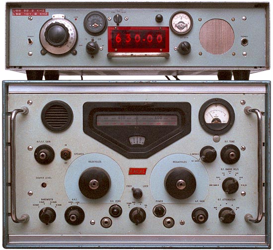
Part 1 of 5: The Racal RA17 was arguably one of the finest short-wave radio receivers ever built using valve technology, so much so that it set the standard for receiver performance well into the 1970s. The reason for its success lay in its excellent frequency stability, low noise, and EMP hardness; all of which proved to be a difficult act to follow using early transistor technology. I first met, and fell in love, with the RA17 in 1969, when I was given the job of setting one up as a training exercise; but not being a Government department, I was unable to own one for myself until they came onto the surplus market in quantity in the late 1970s and early 80s. Even today, the RA17 is still a good receiver, but it lacks many of the features that modern working practice demands. It is relatively future-proof however; and it is possible, without modifying it in any way if so desired, to provide adapters to make good many of its shortcomings. If one is to use the RA17 (rather than put it on a very strong shelf and admire it) there is room for improvement in the following areas: Frequency Readout: The film-scale readout and 100KHz comb-spectrum calibrator was a tremendous improvement over earlier communication receiver designs, but it is a wonder that by the late 1960s, Racal did not modify the RA17 / RA117 to incorporate digital readout. It seems that the company was busy trying to promote the all-transistor RA217; and had no desire to update the venerable classic, even though it was superior to its replacement. The RA17 however, has an interpolation receiver VFO output at PL11 (next to the VFO valve V12) and this can be taken straight to the input of a DFM. The 1MHz internal reference is also available on the back panel, so that the DFM and receiver can both be locked to the same reference and calibrated simultaneously. Reception Modes: The RA17 has no facility for receiving FM, and its provision for receiving SSB and CW consists of a BFO, injected straight into the AM detector according to best 1930s practice. The problem with this type of BFO implementation is that it overloads the AGC system, forcing the use of manual RF gain control, and makes it impossible to obtain readings of RF level. The lack of proper SSB reception facility was of course addressed by Racal in the form of the RA63 SSB Adapter; but RA63s are difficult to obtain. A perfectly satisfactory alternative is to take the RA17 IF output and feed it into a simple product detector. When I bought my RA17, I deliberately chose one of the specialised models (RA17C18) which has no BFO, so that I would be forced to build it a product detector before I could use it (I was also a student at the time, and RA17Ls were more expensive). Audio quality: The RA17 bucked the communication receiver trend by having a loudspeaker on the front panel. This feat of ergonomic brilliance was marred however, by the audio quality, which for moderate periods of listening, constitutes a cruel and unusual form of punishment. It is best to bypass the receiver audio system altogether, and to bypass the AM detector, which is merely a diode rectifier. It is of course, standard practice in most AM radios to use a simple diode detector, but nowhere is there evidence that this is a good idea. A phenomenal improvement in AM quality is possible by using a precision rectifier stage, which also gives a response almost down to DC and a truly linear representation of RF level. |
RA17 Adapter overview:

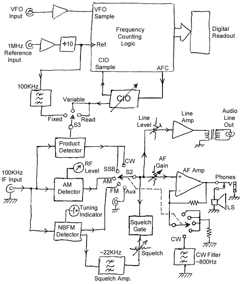
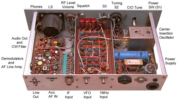
| The RA17 Adapter discussed in this article combines digital readout, precision AM detector and level meter, product detector, NBFM detector, audio stages, and CW filter into one unit. The original was designed and built in 1981, using technology which was perhaps a little old-fasioned even then, but it should serve to illustrate the necessary principles for those interested in using more up-to-date techniques. A block diagram is given |
below.

| An audio filter for CW is provided in this design because the RA17C18 used by the author does not have an IF crystal filter. The frequency counting system measures the interpolation receiver VFO and calculates IF offset to display the KHz part of the listening frequency. The MHz part is obtained from the RA17 'Megacycles' dial as usual (a discussion of how to implement full frequency readout is given in part 4). When the variable frequency carrier insertion oscillator is in use, the counter measures both VFO and CIO and displays the listening frequency corresponding to zero-beat. The demodulation mode switch (S2) has five positions: CW, SSB, AM, FM, and Auxiliary audio input. SSB and CW are the same except that, in the CW position a filter is inserted into the feedback loop of the audio power amp. The audio line amp does not have a CW filter, since the principal purpose of the line output is to permit tape-recording of telephony signals (and nowadays to feed RTTY, FAX, etc. into a computer sound card). All three detectors are permanently connected to the IF input, the FM detector also providing a centre-zero tuning meter, and the AM detector an RF level meter; CIO injection is however suppressed except in SSB and CW modes. The CIO injection switch (S3) has three positions, 'Fixed', 'Variable', and 'Read'. In the 'fixed' position, the CIO is fed with an exact 100KHz signal derived by dividing the 1MHz reference by 10. This position is used for calibrating the receiver onto frequency standards broadcasts, and for finding the exact carrier frequency of AM stations. The 'Variable' and 'read' positions are the same, except that in 'read' mode, the counter is switched to display the frequency of the CIO. To decode USB transmissions, the receiver bandwidth is set to 3KHz, and the CIO is set to 98.2KHz. To decode LSB, the CIO is set to 101.8KHz. The 'read' setting is also used for calibrating the CIO onto the centre of its tuning dial. In retrospect, the procedure for changing sidebands is rather slow, and it would have been better to have provided two extra positions: 'USB' and 'LSB', with an additional crystal oscillator and two crystals for the IF-1.8KHz and IF+1.8KHz feeds. |

» Part 2
D.W. Knight. 1981, 2000
Home | Ra17 index || next