|
|
|
|
|
|
6.5 Magnitude-Difference Bridges. Part 3.
|
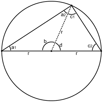
14.1. Circumscribed circle theorem. 14.2. Quadrature theorem. |
15. Conductance bridges. >>> Writing in progress! |
|
14: Phasor theorems: Knowledge of the following theorems is reqired for an understanding of conductance and phase bridges. |
|
14.2. Quadrature theorem: 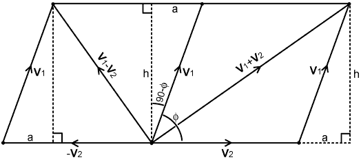 Using the definitions given in the diagram, the magnitude
of the sum of V1 and V2 is: |
|
15. Conductance Bridges: Recall that admittance is defined as: Y = 1/Z = G + jB Where G is conductance and B is susceptance. A pure reactance Xp (say), has a pure susceptance Bp = -1/Xp. When two admittances are placed in parallel, the new admittance is obtained by simple addition. Hence if an admittance jBp is placed in parallel with an admittance Y we get: Y + jBp = G + j(B + Bp) It follows, that when a pure reactance is placed in parallel with an impedance, conductance is unaffected. When the locus of an impedance (i.e., its point in the Z-plane) is constrained by the condition of constant conductance, its path in the Z-plane is a circle that has the two points 0+j0 and R+j0 on opposite ends of a diameter. A conductance (G) transmission-bridge is a bridge that will remain balanced when an arbitrary (but non-zero) pure reactance is placed in parallel with the target load resistance. The utility of such an instrument lies in the fact that, if an operation is performed to move an impedance onto the constant conductance circle corresponding to G0 = 1/R0, then the impedance matching process can be completed by adjusting a reactance placed in parallel with the load. Conductance is the reciprocal-space counterpart of resistance. Therefore the balance equation for a conductance bridge can be obtained by taking the equation for a resistance bridge and substituting Vv for Vi and vice versa. Looking at the problem formally however, we should start by defining Vv and Vi as admittance analogs, and so (with reference to Table 12.1) take Vv to represent G0 (assuming B0=0), and Vi to represent Y. We then specify that the bridge must balance when G=G0, i.e., Y=G0+jB, regardless of the value of B. Now we observe that: G0 +jB -2G0 = -G0 +jB has the same magnitude as G0+jB. The solution is therefore: |Y - 2G0| = |Y| when G = G0 which, when replaced by its analogs gives:
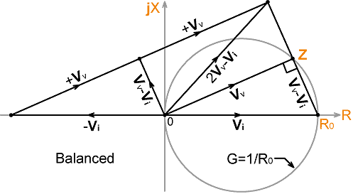
This balance relationship can be proved by considering the phasor relationships shown in the diagram below: |
|
When R0 and Z lie on the same constant
conductance circle in the Z-plane, Vv
and Vi lie on a corresponding circle
in the sample-voltage space. When that situation prevails, theorem 14.1 tells us that the phasors Vv and Vv-Vi are in quadrature. When two phasors are in
quadrature, the magnitude of their sum is equal to the magnitude
of their difference (theorem 14.2).
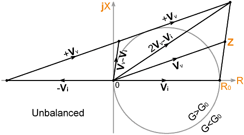
Hence: | Vv + Vv - Vi | = | Vv - ( Vv - Vi ) | i.e.: | 2Vv - Vi | = | Vi | The corollary, of course, is that: |2Vv-Vi| ≠ |Vi| when G ≠ G0 A phasor diagram corresponding to that situation is shown below: |
|
Notice here that when Z is inside the G0
constant conductance circle, then G>G0,
and vice versa. Conductance has a reciprocal relationship with
impedance and so increases as the origin of the Z-plane
(0+j0) is approached. Also notice the polarity information:
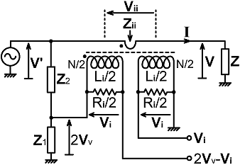
When |Vi| > |2Vv-Vi| , G > G0 It follows, that when the two rectified outputs of a conductance bridge are used to drive a centre-zero galvanometer, the +|Vi| output should be connected to the meter's (+) terminal. A prototype bridge circuit is shown below. In this case, we define the output of the voltage-sampling network as 2Vv, and the outputs of both current-transformer secondary windings added together as 2Vi. Thus we have: |
|
2Vi = I Zi
/ N = V Zi / (N Z) where: Zi = Rik // jXLi (Rik being the effective secondary load after taking losses into account) and 2Vv = V' Z1 / (Z1 + Z2) where: |
 |
|
V' = V + Vii = V
[1 + Zii/Z] i.e.: V' = V [1 + Zi/(N² Z)] As before, Vv=Vi when Z=R0; and so, due to the factor of 2 in both sample-voltage definitions, the network solution is the same as for a Z bridge; i.e.: Zi / (N Z) = [1 + Zi/(N² Z)] Z1 / (Z1 + Z2) Which can be rearranged to give: |
|
Z1 |
|
Zi |
|
N |
|
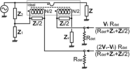
| When the bridge outputs are loaded, a port balancing network ( ZV = Z1//Z2 ) is needed in order to achieve optimum accuracy. The voltages obtained are shown in the diagram below: |
|
For accurate DC port balancing, Z2
should be a DC open-circuit. Notice also that the ZV network has been placed on the earthed side
of the winding used for the "Vi"
output. It can go on either side in principle; but the capacitance
of the Faraday-shield (if used) forms part of Z1,
and so the arrangement shown gives best symmetry. The phasing
of the "Vi" winding is,
of course, irrelevant because |Vi|
= |-Vi|. The two secondary windings
should however be electrostatically isolated; i.e., they should
not be in physical contact, and they should definitely not be
wound as a bifilar pair. . |
|
>>>>>>>> Writing in progress. Citation: Broad-band reflectometers at high-frequencies. R T Adams, Alexander Hovarth. Electrical Communication. 32(2), 1955. p118-125. Resistive voltage sampling, resistive or transformer current sampling, 300KHz - 30MHz. Resistance, conductance and phase bridges are described. >>> Less severe loading defect because Ri << Rdet.. G bridge balances when Z = R0 // jX , regardless of X. It was shown in [A6.4] that balance error due to current transformer secondary parallel reactance is equivalent to a reactance of opposite sign in parallel with the load. Since the balance point of a G bridge is immune to such reactance, the bridge requires neither LF compensation nor HF neutralisation. If we use CVS however, LF comp resistor provides diode DC return (but there is no need to make it adjustable). Amplitude balancing is required for accurate sysnthesis of the vector 2Vv-Vi. . |
|
>>>> Phase bridges -- Generic scheme (DBM), quadrature networks. Unloaded transformers. Transparent (broadband matched) phase bridge. -- Poles and zeros. Diode limiter solution. Distortion? - put the TR relay after the bridge. |
|
Combination bridges. - switching off current transformers by
shorting Faraday shield. Tapping the LF comp resistor for multi-function bridges pros and cons of getting Vi/2 from the VS network or the summing network. Double diode rectifier. |
© D W Knight 2010, 2013
David Knight asserts the right to be recognised as the author of this work.
|
|
|
|
|
|
