|
|
|
|
|
|
|
X-dipole: EZNEC Modelling of Zin
|
One important consideration in implementing an HF general coverage
dipole antenna with balanced-wire feedline is that of avoiding
awkward input impedances. In particular, impedance magnitudes
exceeding about 5000W may be outside
the operating range of typical matching networks, and if highly
reactive, may give rise to excessive losses in the matching network.
In general, such problems are confined to low-frequency operation
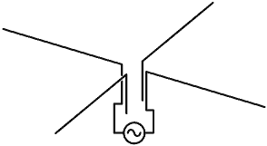
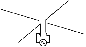
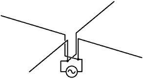
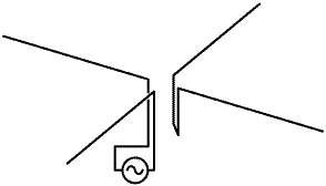
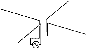
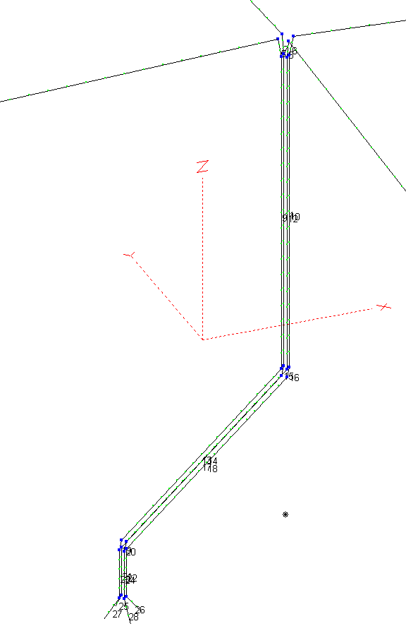
(160m, 80m and 40m). A dipole antenna cut to be about l/2 on 160m (and l on 80m), will have a low input impedance on 160m and an extremely high input impedance (8 to 16KW) somewhere in the 80m band. For the NLO installation however, the feedline length will be of the order of l/4 on 80m, effecting a transformation from high to low impedance. Hence, an awkward impedance for driving the antenna on 80m is not to be expected but, depending on the choice of wire lengths, awkward impedances on 160m and 40m are a distinct possibility. Modelling with NEC is one way to investigate the awkward impedance problem, but there are limitations to this approach for the present application. Firstly, the Observatory building complex is directly below the central part of the antenna; and it is impractical to take all of the wiring, pipework, equipment and building materials into account. Secondly, the isolated transmission line approach favoured for most simulations will not be valid for an asymmetrically connected 4-wire line. This means that the transmission-line system has to be included in the wire model, with attendant problems of segment boundary alignment, element proximity, and inaccurate field simulation in the region of sharp bends. Hence, the best that can be expected from simulation is an idea of the frequencies at which the nasty impedances will occur; taming the beast in practice being a matter of pruning the wires if a problem occurs. Initial simulations indicate that making the four horizontal radiators as single 50m long wires will give an excessively high input impedance in the 160m band. The optimum length appears to be 40 to 45m. The far end of the South wire will be too close to the Observatory boundary if lengths in excess of 50m are used. Wire model: The central antenna mast is at the back of the building (mounted on the North wall using T&K brackets). The bottom section is 48mm diameter aluminium tubing from a height of 1m to 7m. The top section is fibreglass, from a height of 7m to 13m. A straight coupler of about 0.3m length causes the conductive section to extend to a height of 7.15m. The radio room is at the front (South side) of the building, displaced diagonally from the mast at a horizontal distance of about 10m. Hence the feedline must cross the roof. The flat roof of the building is at a height of about 3m. When feeding a horizontal dipole antenna, interaction between the antenna and the feedline is minimised by projecting the feedline at right-angles to the radiator for as great a distance as is possible. This means that the feedline should drop vertically to a height where, from the radiator's point of view, the roof-crossing section merges with the general conductive clutter of the building itself. This topology has the additional advantage that it minimises the risk that the feedline will snap when the central mast sways in the wind. The wire model is constructed accordingly, with the feedline dropping from 13m to 4m, then undergoing a 90° bend to travel South-West for a distance of 10m. A further drop of 2m with splayed ends represents termination at the radio room. The feedline spacing has been set at 0.2m on the diagonal (14.1cm x 14.1cm square) this being a reasonable choice. The overall arrangement assumes that, in practice, the axis of the feedline will be kept at least 1m from the roof surface, and 1m away from the metal section of the central mast. The central mast was found to make no significant difference to early simulation results, and so the structure is omitted from the simulations given here. The existing HF beam antenna installation just outside the radio room has not been included in the model. The EZNEC+ v5.0 program was used for the simulations. The input files listed below use more than 500 wire segments and may need to be modified for use with some versions of EZNEC. The models used include wire losses and are simulated over a realistic ground. The four radiator wires are 45m long and slope from a height of 13m at the central mast to 11m at the far ends. |
 |
|
 |
 |
 |
|
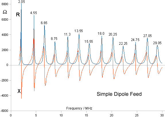
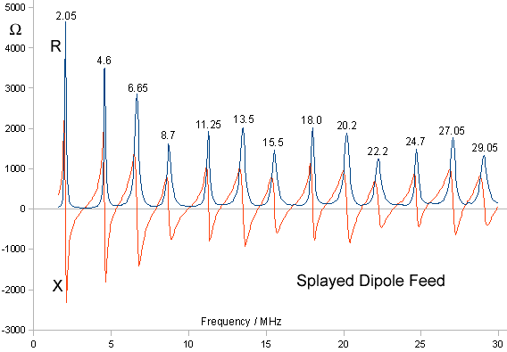
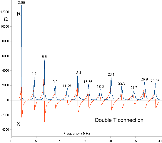
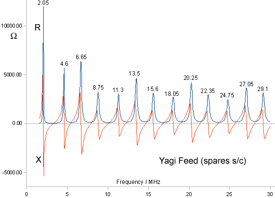
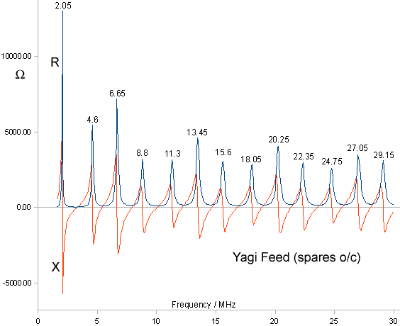
From the graphs shown above, it can be seen that the system parallel
resonance frequencies are preserved regardless of connection,
but the actual input impedance at a given frequency will depend
on the chosen feeding configuration. The parallel resonance at 2.05MHz may be problematic when working on 160m. The resonance can be shifted to higher frequency by shortening the radiators or the transmission line, but there is danger of shifting the 6.65MHz resonance into the 40m (7.0 - 7.2MHz) band. Since practical considerations will determine the final transmission line length, there is no point in altering the wire model at this stage. The important point is that shifting an awkward impedance in any one of the possible feeding configurations will serve to cure the problem for all of the other configurations. It is proposed that, for genaral operation, the installation is provided with a desktop automatic ATU. In the event that such a matching system should complain that the input impedance is out of range, it is of course possible to provide additional network components to solve such problems. Take, for example, the input impedance of the simple dipole arrangement at 1.9MHz, which is predicted to be 978 +j2080 W. Placing a capacitance of 40pF in series with the feed (80pF in each side) will make the input resistive, and a 16:1 balun transformer (4:1 turns ratio) will bring it to 61W. It is perfectly feasible to find a combination of capacitors and balun which will bring the antenna into range of the tuner over the whole band. |
© D W Knight 2008.
David Knight asserts the right to be recognised as the author of this work.
|
|
|
|
|
|
|
