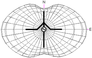
X-Dipole: Far-field simulations; 80m band.
(Calculations performed using EZNEC+ v5.0)
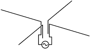
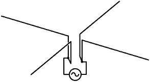
Simple dipole feed:
N and S wires driven.
E and W wires unconnected.
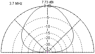
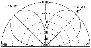
Model: x45dipole.ez (simulation
frequency set to 3.7MHz).
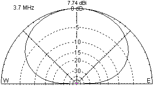
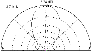
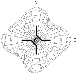
Maximum low-angle radiation is broadside to the wire. Pattern
can be rotated through 90° by connecting the transmitter
to the E and W wires.
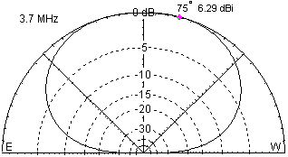
Shown below: slices through N-S and E-W directions. For radiation
at an elevation of 45°, there is a difference of about 18dB
(3 S-points) between N-S and E-W. For 80m DX working, operators
and worked stations will definitely notice the difference between
the two possible pattern orientations.
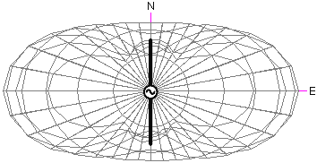
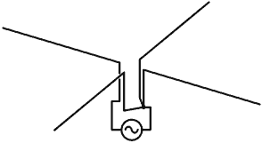
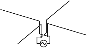
Splayed dipole feed:
N and E wires joined
S and W wires joined.
Model: x45splay.ez (simulation
frequency set to 3.7MHz).
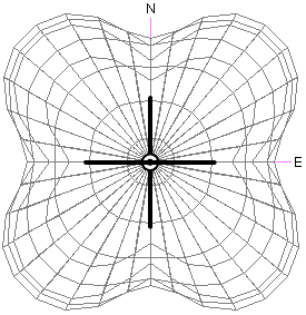
A more omni-directional pattern is achieved in comparison to
the simple dipole configuration. Gain in the vertical direction
is unaffected.