|
|
|
|
|
|
|
X-Dipole: Far-field simulations; 160m band.
(Calculations performed using EZNEC+ v5.0)
|
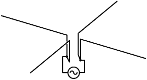
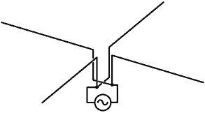
Dipole feed (NVIS): Apart from a 45° rotation, on 160m there is practically no difference in radiation pattern and maximum gain between the simple dipole feed and the splayed dipole feed (shown right). The splayed dipole has the lowest input impedance and is therefore easiest to match and gives the best matching-network (ATU) efficiency. |
 |
|
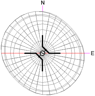
Model: x45splay.ez . The radiation pattern shown on the left occurs when one end of the generator is connected to the N and E wires, and the other end is connected to S and W wires. This synthesises a virtual dipole running SW to NE. Maximum low angle radiation occurs broadside to this virtual wire, i.e., in NW and SE directions. The difference between end-on and broadside is however small (< 2dB). Maximum radiation occurs in the vertical direction, with a gain of 4.2dBi. |
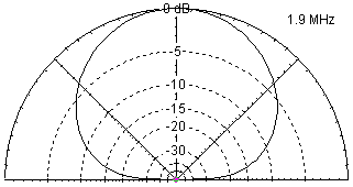
| Shown right is a slice of the radiation pattern along the E - W direction. This pattern is optimal for local (within 1000Km) NVIS communications. |
 |
| The simple dipole model was used for input impedance calculations, and may be used for far-field simulations for comparison with the splayed dipole if so desired: x45_dipole.ez . |
|
Double-T feed (Top Null): Strapping the antenna to make two long wires which cross at the centre, and driving the two wires in opposition, produces a null in the vertical direction. The disadvantage of this configuration for 160m working is that it suffers from high ground losses (max gain: -4.95dBi), but it offers the facility to suppress NVIS signals in favour of more distant stations. |
 |
|
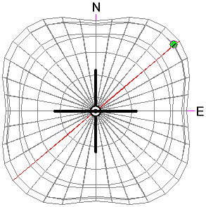
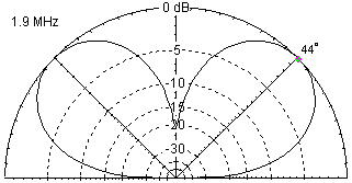
Model: x45_2T.ez . Shown left: radiation pattern from vertically above. The slice marked in red is shown below. |
| The depth of the top null is -26dB for the model; but asymmetry due to the antenna environment will reduce this figure in practice. |
 |
|
Yagi feed (Cardioid): If the antenna is fed as a V-dipole, with the spare pair of wires either joined or left open-circuit, the radiation pattern is similar to that of the simple or the splayed dipole. If a reactance is connected to the spare pair however, a parasitic element of variable electrical length is formed. If the electrical length is shorter than that of the driven dipole, the parasitic element becomes a director, and if longer, a reflector. |
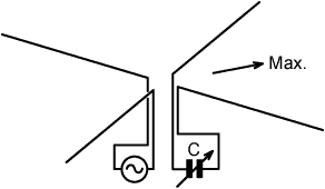 |
| On the 160m band it requires a large positive (inductive) reactance to turn the parasitic element into a reflector; and it turns out that the necessary inductance is impractically large (>>60mH). It is much easier (and considerably more efficient in practice) to obtain a large capacitive reactance by attaching a variable capacitor; in which case the parasitic element becomes a director. |
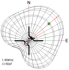 |
Model: x45_yagi_50pF.ez
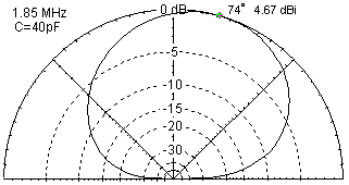
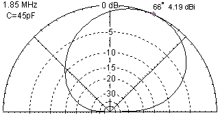
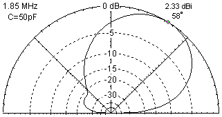
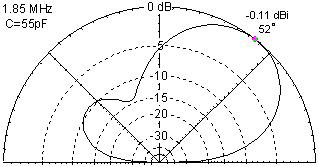
. Shown left is the effect of driving the South and West wires and connecting a 50pF capacitor between the North and East wires. The actual capacitance required depends on the operating frequency. 50pF is appropriate to the model operating at 1.85MHz. The radiation pattern for the slice marked in red is shown below for various capacitances. |
|
Shown right is a sequence giving the effect of sweeping the director
capacitance from 40 to 60pF for a driving frequency at which
maximum front-to-back ratio occurs when the capacitance is about
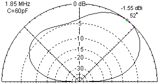
50pF. When the S and W wires are driven, and the capacitor is across the N and E wires, maximum radiation is in the NE quadrant. The direction can, of course, be switched into any one of the four quadrants by swapping wires. For a very small capacitance (open circuit) or a very large capacitance (short circuit), the radiation pattern reverts to that of a low horizontal dipole, i.e., maximum radiation in the vertical direction. Open circuit and short circuit models were used for input impedance calculations, and may be used to obtain far-field simulations for comparison purposes if so desired: Open circuit: x45_yagi_oc.ez. Short circuit: x45_yagi_sc.ez . When he spare pair is left unconnected, the maximum gain is 3.2dBi at 1.85MHz. When the spares are shorted together, the gain is 2.0dBi. For normal NVIS communications, it is best to use the splayed dipole configuration discussed earlier (4.0dBi at 1.85MHz), but the differences are negligible in terms of perceived signal strength. |
|
|
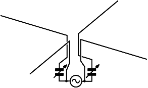
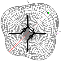
Driven Reflector. (Pseudo Yagi). Capacitors connected from gen. termimal to adjacent wire (produces Yagi-like radiation pattern with pronounced back lobe and deep intermediate null): Model: x45_U-phased_2C.ez . |
 |
 |
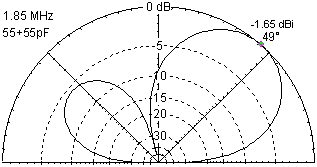 Slice through the SW - NE direction. |
|
Phased Array connections: Various other interesting nulls and circular polarisation effects can be achieved by using a pair of ganged variable capacitors or a pair of ganged variable inductors. x45_X-phased_2L.ez . x45_N-phased_2C.ez . |
© D W Knight 2008.
David Knight asserts the right to be recognised as the author of this work.
|
|
|
|
|
|
|
