All Mode Transmit, Receive and Digital Readout
Adapter for the RA17.
By D.W. Knight.
Version: 1.00 (Unicode)
Part 1.
This article should be read in conjunction with the original RA17 adapter article.
This article describes preliminary design work which was carried
out with a view to developing an adapter for the RA17, to provide
a transmitter output, and to add a level of receiver functionality
in keeping with modern conditions and practices. The information
given here should be regarded purely as a design exercise. No
hardware has been built, but the work carried out may nevertheless
be of interest to others.
The basic requirements under consideration are as follows:
· Full digital frequency readout.
· Reception modes: AM, NBFM, USB, LSB, Channel centred
BFO, Variable BFO, Aux audio in.
· Automatic mode switching for Wadley front-end or LF Adapter.
· CW audio filter.
· Fine tuning control
· Clarifier (RIT) control.
· Transmitter output: NBFM, USB, LSB, CW, Tune.
· CW side-tone monitor.
· Speech Automatic Level Control (ALC).
Factors which mitigate against this project are the age of the
receiver, and its performance shortcomings in the following areas:
· Poor IF filter performance: filter skirt responses, particularly
of the all-important 3KHz filter, are too high for modern band
conditions.
· Poor image rejection: signals +200KHz relative to the
wanted signal are only -65dB (the RA117 does not suffer from this
problem).
· Extremely poor AGC characteristics.
Conversion Schemes:
Most of the design information for a receiving adapter with full
frequency readout has been given in the original adapter article,
particularly in part 4. The major design issue at this stage is
consequently that of how to obtain a transmitter output at the
receiving frequency. The Racal companion transmitter for the RA17
uses the Wadley loop in reverse; but since this approach requires
construction and setting-up of various high-frequency bandpass
filters, it must be considered beyond the capabilities of most
amateurs. It transpires however, that once a transmission signal
has been produced on the interpolation receiver frequency (in
normal transceiver fashion); a one-step translation, using a heterodyning
signal at an integer number of MHz, is sufficient to generate
the required output frequency and preserve sideband polarity.
For the sake of any RA117 users who may wish to adapt the information
given here, some consideration of RA117 signal processing and
design issues will be given. It is however, not the author's intention
to design an adapter for the RA117.
The signal processing which takes place in the RA17 or RA117 (when
using the Wadley front-end) is shown in the diagram below. In
this case, the input frequency fc is defined
as N+Δf, where N is the 'Megacycles' dial setting, and Δf
is the 'Kilocycles' dial setting. The incoming signal is assumed
to have sidebands fc+δf (USB) and
fc-δf (LSB), and the diagram shows
what happens to them:
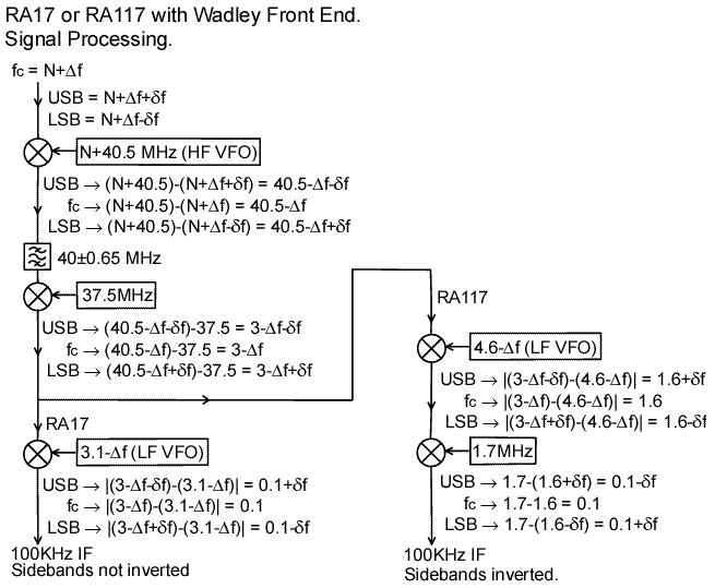
The outcome of the RA17 signal processing is that; although the
interpolation band is inverted (ie., the system tunes HF as the
interpolation receiver tunes LF), sideband polarity is conserved.
The additional conversion step in the RA117 causes sideband inversion.
When the RA17 or RA117 is used with an LF adapter, the Wadley
loop is disabled, and the following situation prevails:
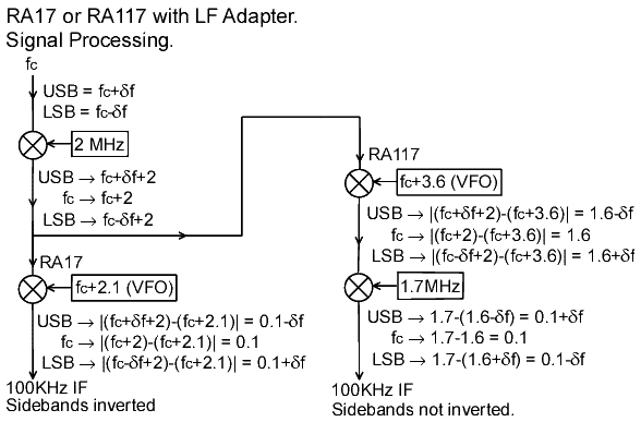
In this case, the interpolation receiver tunes HF as the system
tunes HF. Sideband inversion occurs in the RA17 but not in the
RA117. Immediate caveats are; that on switching on the LF adapter,
the digital frequency readout must count upwards from the
LF VFO, and the carrier insertion frequencies for USB and LSB
must be swapped.
An outline signal processing scheme for a transmitter exciter
is shown below. The carrier generator, in this case, can be assumed
to be a synthesiser locked to a sub-multiple of the RA17/117 1MHz
reference, producing 98.2KHz or 101.8KHz as required for SSB,
and 100KHz for all modes requiring a channel-centred carrier.
FM can be produced by feeding audio to the control terminal of
the synthesiser VCO.
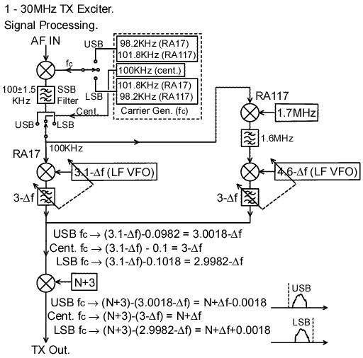
Note that having translated the signal to 3-Δf MHz using
a conventional transceiver architecture (when using the RA17 at
least), it is only necessary to mix the signal with an oscillator
at N+3 MHz to obtain the desired output and conserve sideband
polarity. If the 'N+3' oscillator is locked to the RA17 1MHz reference,
the transmitter output frequency will be exactly the same as the
receiving frequency; and special arrangements will be required
to cause the two to deviate (ie., for RIT). Note that the TX output
also contains an unwanted signal at N+6-Δf, and some residuals
at N+3 and 3-Δf MHz due to any mixer imbalance. Filtration
of the output is therefore required.
There are few legitimate reasons why anyone would want to produce
SSB at frequencies below 1MHz, but the TX exciter might conceivably
be used to produce CW at 136KHz, and it might be used as a source
of test signals at say 100KHz, or 465KHz. There is also little
point in excluding the facility as an option; since all it takes
is to reverse the designations of the USB and LSB carrier frequencies,
and set the final conversion synthesiser to 2MHz (as follows):
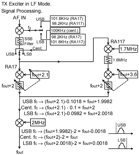
As before, the output also contains unwanted components; in this
case fout+4 and the mixer residuals at
2 and fout+2 MHz, all of which can be removed
with a low-pass filter. Harmonics of the output frequency however,
present an additional filtration problem.
Generalised converters:
The two possible single-step heterodyning schemes for converters
feeding the RA17 interpolation receiver can be summarised as follows:
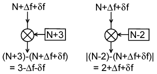
It is sufficient to show only the upper-sideband case to determine
the converter properties; ie., sideband inversion occurs if the
upper sideband comes out on the lower side of the carrier, and
vice versa. Band inversion occurs when Δf is subtracted
from the upper interpolation band limit, but not when it is added
to the lower limit. In the RA17 case, when sideband inversion
occurs in the converter, it does not occur overall because the
interpolation receiver also causes sideband inversion (the converse
is true for the RA117). The two possible conversion methods will
be referred to as the 'N+3' and 'N-2' translation schemes.
The TX exciter in Wadley mode is an example of an 'N+3' converter.
The LF adapter is an example of an 'N-2' converter (where N=0).
In principle, it is possible to design converters using either
of these translation schemes to make a receiver or transmitter
operating on any frequency (ie., >30MHz). The problem however,
is the low operating frequency of the interpolation receiver,
which makes converter image-frequency suppression increasingly
difficult as the operating frequency is increased. Consequently,
only multiple conversion schemes are viable for >>30MHz
converters. The four possible double-conversion schemes are as
follows:
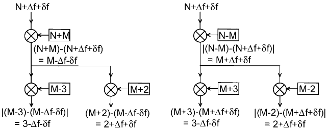
It turns out that all of the above schemes are equivalent either
to an 'N+3' or to an 'N-2' converter. This also follows from the
observation:
(N+M) - (M-3) = N+3
(N+M) - (M+2) = N-2
(N-M) + (M+3) = N+3
(N-M) + (M-2) = N-2
(The Wadley loop is an 'N+M, M-3' converter, where M=40.5).
This principle can be generalised to an arbitrary number of conversion
steps; and consequently, all possible converters can be accommodated
using the behaviours built into the adapter to satisfy its basic
specifications. In effect, the LF adapter is a special case of
an 'N-2' converter which requires no MHz readout. The Wadley loop
is a special case of an 'N+3' converter with hardware in the adapter
to calculate the MHz readout. All other converters might assert
the category to which they belong, and submit MHz data, via a
port on the back panel.
Negative Frequencies:
The HF VFO dial of the RA17 has markings from 0 to 29MHz. In addition
to these ranges, there can also be found unmarked signal peaks
for 30 and 31 MHz, and (as recently pointed out to the author
by Rob Filby) a peak for -1MHz. When the MHz selector is set to
-1, the receiver tunes from -1 to 0 MHz, ie., it covers the same
range as the LF adapter, and, as when using an LF adapter, the
receiving frequency must be read from the lower (red) reversed
'kilocycles' tuning scale. Performance of the RA17 on this unofficial
-1MHz range is very poor, partly because the preselector tuning
must be set to 'wideband', but the exercise serves to illustrate
the point that an N-2 converter is the negative frequency analogue
of an N+3 converter, and vice versa. The sideband inversion which
occurs when changing between N+3 and N-2 converters reflects the
fact that a negative frequency upper sideband is a lower sideband.
Author's note (19th Dec. 00): Prior to acquisition of an
LF adapter, I could never understand why Racal did not opt for
the N+3 translation scheme, to make the adapter tune in the same
direction as the Wadley front-end. Having now acquired an RA137,
and experienced the bizarre ergonomics firsthand, I was prompted
to study the circuit to try to see why it was done like that.
After some deliberation, I can only speculate that nobody thought
of doing it the other way at the time. There seems to be no earthly
reason why the LF adapter frequency doubler module cannot simply
be replaced directly with a frequency tripler, to make the tuning
direction the same as for the 1-30MHz ranges.
Part 2 >>
D.W.Knight. 07/2000.
Home | Ra17
index.


