By David W. Knight. G3YNH
Version: 1.00
|
Part 4 of 5. Frequency Counter. The basic principles of IF-offset frequency counting are explained in the author's digital frequency readout article. Frequency Counter: Circuit Diagram (72K GIF, 839 x 1153 pixels). Refer to the above circuit diagram while reading this section. The RA17 interpolation receiver tunes from 3 to 2 MHz as the set tunes from N to N+1 MHz. The interpolation VFO correspondingly tunes from 3.1 to 2.1 MHz to produce the 100 KHz IF. To produce a digital 'Kilocycles' readout (assuming the 10Hz resolution adopted), it is therefore necessary that the counter should read 000.00 when the VFO is at 3100.00 KHz, and 999.99 when the VFO is at 2100.01 KHz. The solution used is to load an offset of 100_00 into a 5-digit (BCD) count register (the underscore indicates where the decimal point is placed in the display), and count downwards from pulses derived from the VFO (for a period of 100ms). The resulting modular arithmetic is illustrated in the table below: |
| VFO Input Pulses | Register Contents | VFO Input Pulses | Register Contents | |
| 0 | 100_00 | 2100_00 | 000_00 | |
| 100_00 | 000_00 | 2100_01 | 999_99 | |
| 200_00 | 900_00 | 2200_00 | 900_00 | |
| .. | .. | 2300_00 | 800_00 | |
| .. | .. | 2400_00 | 700_00 | |
| 1000_00 | 100_00 | 2500_00 | 600_00 | |
| 1100_00 | 000_00 | 2600_00 | 500_00 | |
| 1200_00 | 900_00 | 2700_00 | 400_00 | |
| .. | .. | 2800_00 | 300_00 | |
| .. | .. | 2900_00 | 200_00 | |
| 1900_00 | 200_00 | 3000_00 | 100_00 | |
| 2000_00 | 100_00 | 3100_00 | 000_00 |
|
The IF offset may be introduced either by pre-setting the count
register (ie., when the CIO is fixed at 100KHz or not in use);
or by counting up from pulses derived from the variable CIO,
in which case any deviation of the CIO from 100KHz is automatically
accounted for. The counter timing waveforms are produced by dividing the 200Hz reference signal in two quinary (divide by five) counters, which produce the signals denoted A1, B1, ..., C2. The period of C2 is 125ms (100ms off, 25ms on), and the inverse of C2 is used as the 100ms sampling interval. The outputs from the divider chain and the signals derived from them are shown below: |
|
A1, B1, and C2 are gated together to produce the signal denoted
"Sample Select Clock". This signal is used to toggle
the 7474 'sample select' flip-flop, so that the sampling gates
for the CIO and VFO inputs can be activated alternately when
the settings of S2 (demodulation mode) and S3 (CIO mode) permit.
Also derived are a preset signal for the count register, and
strobe signals for transferring the contents of the count register
into the display and AFC registers at appropriate times. The
signals denoted 'Read CIO' and 'Read VFO' are not derived explicitly,
but are shown on the graph to indicate the positions of the data
acquisition windows. Note that the count register preset signal
has a potential glitch (marked with a *) which can occur due
to propagation delays in the sample select flip-flop and subsequent
gates. This is eliminated by inserting a 40ns (approx.) delay
into the sample select clock before combining it with the flip-flop
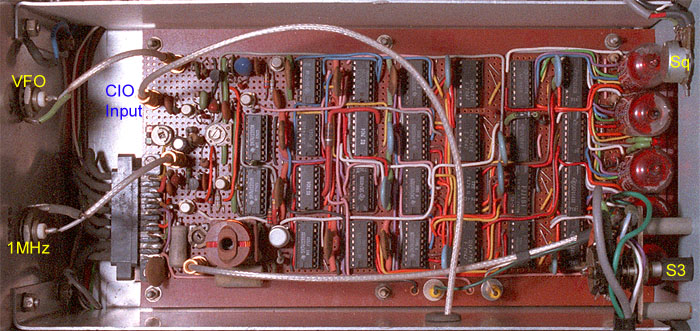
output. The counter has three modes of operation: Fixed Offset Mode is used when the variable CIO is not in use. In this case the sample select flip-flop is jammed in VFO mode, and the count register is preset to 100_00 before down-counting commences. Counting occurs for 100ms, then the sample gate is closed for 25ms while the data is strobed into the display and the count register is preset ready for the next cycle. The overall data refresh rate is 8Hz. Variable Offset Mode is used when the Variable CIO is in use. In this case, the sample select flip flop is allowed to toggle, and the count register is preset to 000_00 (ie., reset) before the start of each cycle. At the end of the CIO up-counting period, the least significant digit of the CIO frequency is loaded into the AFC register (discussed shortly). At the end of the VFO down-counting period, the register has accumulated CIO freq. - VFO freq. (modulo 100000), which is the required 'Kilocycles' readout to 10Hz. The overall refresh rate is 4Hz. Read CIO Mode is engaged when S3 is placed in the read position and S2 is set to SSB or CW. In this case the sample select flip-flop is jammed in CIO mode, and the count register is preset to 000_00 before up-counting commences. After counting, the display and AFC registers are strobed simultaneously, and the display shows the CIO frequency to 10Hz. The overall refresh rate is 8Hz. The display in the original counter uses nixie tubes and 74141 decoder ICs, a choice which is perhaps not to eveyone's taste. These can be replaced by 7-segment LEDs and 74LS47 decoders if so desired. The chip count can also be reduced slightly, by replacing four of the 7475 display registers with 2 x 74xx373 octal D-type latches. There is no reason why most of the logic chips cannot be replaced with 74LS or 74HCT series parts, although the 74141 is only available as a standard TTL part. The possibility of using 74HCT (60MHz) CMOS is interesting, because the power consumption will then be considerably reduced, and each 74HCT output is capable of sinking 4mA. 74HCT chips can therefore be used to drive the 74141 decoders (-3.6mA source max) directly, if used. Note that for interfacing with TTL, 74HCT series CMOS must be used. The 'T' indicates CMOS using TTL logic levels, and must not be confused with standard 74HC series CMOS. Counter Compartment: View of the original counter in its screening trough. Note that the VFO amp., the 1MHz amp., the CIO TTL buffer, and the fixed 100KHz CIO output and BPF are all on this board. |
|
CIO AFC System: It is a perfectly straightforward matter
to build a stable 100KHz VFO, and so frequency locking of the
CIO is unnecessary. It was included however, so that the author
could evaluate the idea of using counter register contents to
control oscillators in other applications. A register storing
only the least significant digit (LSD) of the CIO reading is
connected to a 74141 BCD to decimal decoder, and the decoder
output is used in such a way that; if the LSD is 0 - 4, the AFC
voltage falls, pulling the CIO frequency down, and if the LSD
is 5 - 9, the AFC voltage rises, pushing the frequency up. Thus,
after an adjustment of the CIO, the frequency homes on to the
nearest 100Hz step, ie., any frequency which causes the LSD of
the measurement result to alternate between 0 and 9. The 'lock
range' control is adjusted to prevent overshoot, so that a relatively
short (~1sec) time-constant can be used. The circuit locks because,
if the CIO tries to drift up, two zeros are produced in succession,
and the average control voltage falls; and if the CIO tries to
drift down, two nines are produced, driving the average control
voltage up. When the circuit is adjusted correctly, the shift
in frequency from the operator set position is never more than
50Hz. The lock LED circuit is arranged to extinguish the LED when the AFC register contains a 0 or a 9. Given the high saturation voltage of the 74141 output transistors, a 1N4148 diode is placed in series with the LED to ensure that it can be extinguished completely (the 74LS145 would be a better choice). The 'lock LED killer' circuit prevents the LED from illuminating when the counter is operating in fixed offset mode. The CIO AFC system can be omitted completely if so desired, eliminating the 7475 AFC register, the 74141 decoder, and two gates used to produce the AFC strobe signal. The AFC circuitry in the CIO can be omitted, up to and including the 100pF capacitor between the varicap diode and the tuning capacitor. |
Megacycles readout:
|
In the original development work for the adapter, it was envisaged
that the display might show the complete frequency of the receiver
(ie., MHz and KHz), deriving the former from the 40-70MHz HF
VFO of the RA17. With this in mind, an experimental frequency
divider for the HF VFO was constructed, and the necessary counting
logic devised. The plan was abandoned because it was found that
frequency division products could be heard in the front-end of
the receiver, despite careful screening; and thus the cardinal
rule: that the performance of the RA17 should in no way be degraded,
was broken. For those who might be interested in pursuing this
matter, details of the experiments and other design considerations
are given here: The RA17 has no external output for the HF VFO, and so a Megacycles readout can only be obtained by modifying the set. Various electro-mechanical possibilities sprang to mind originally, including coupling a potentiometer to the HF VFO tuning capacitor and reading it with an A-D converter; but for an all-electrical, self-calibrating solution, some form of offset-counting of the VFO frequency is required. The RA17L 1st VFO and associated circuitry is shown below (The RA17 C12 and C18 are similar but V4 is a 6AS6 and connections to pins 6 and 7 are swapped): |
| The obvious place from which to obtain a 40-70MHz VFO output is from the anode of V5. Fortunately, it is not necessary to dismantle the HF VFO unit because the anode load inductor L20 (wound on R18) is located in the central under-chassis compartment of V4 and V8. To evaluate this possibility, the wire from the 32MHz LPF and R26 were unsoldered from the PTFE feedthrough insulator 'Test Point 1' (next to V4 valveholder), and a 10pF capacitor was connected between the feedthrough and the anode end of L20//R18. |
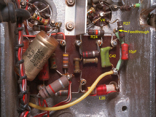
| An earthing tag was also added (above chassis) to one of the V4 valveholder retaining screws, so that a short length of co-ax. could be connected from the feedthrough to a small die-cast box containing a buffer amp. and a divide-by-100 prescaler. |

|
Obviously, the elimination of TP1 is not a good idea in the long
term, and a permanent solution will be to add another feedthrough
next to the original. Note however, that there is little room
in which to do so, and care must be taken to ensure that there
is no interference betwwen the feedthrough and the skirt of V4
screening can (removed for clarity in the picture above). The original prescaler circuit, powered from the receiver's 6.3V heater line, is shown below: |
|
The circuit above did not cause significant detuning of the HF
VFO (which can, in any case, be corrected by adjusting C77 with
the MHz dial set to '29'), nor did it degrade the receiver sensitivity.
The problem experienced however, was that harmonics of the 405
- 695KHz prescaler output could always be heard in the receiver
front-end. The interference was bad with a cable connected to
the output, but still detectable with no cable attached; and
was evidently due to a combination of radiation from the cable,
and leakage into the harmonic mixer compartment and the heater
line. The problem was not considered to be insurmountable at
the time, but it pointed to considerably more experimentation
than was originally envisaged; and in view of the fact that the
RA17 already has a perfectly adequate mechanical MHz readout,
the project was abandoned and the offending prescaler unit removed. With 19 years of hindsight, and in light of certain amount of technological progress, a solution to the problem described above is now obvious: feed the 40 - 70MHz VFO signal into a wideband video-amplifier IC (powered from the heater line as before) and use this to produce a straight VFO output capable of driving a 50Ω line. The line can then be properly terminated at the remote end, and heavily buffered before connection to any counting circuitry. In this way, all frequency components of the VFO output fall outside the receiver operating range, and any VHF pollution caused is likely to be minor in comparison to the HF VFO signal and its harmonics already radiated by the receiver (the HF VFO is disabled when external converters are used with the interpolation receiver). Once an HF VFO output has been provided, an offset-counting system to produce a MHz readout is easy to design; but the ergonomic requirements for a complete frequency readout are not the same as for the simpler 'KHz only' approach. If the display does not show MHz, then the procedure for operating the receiver is unchanged, and the counter merely dispenses with the inconvenience of using the calibrator and estimating frequency from the tuning scale. If the display does show MHz however, then the operator will come to rely on it completely; and it must therefore still read correctly even when the interpolation receiver is tuned past the ends of the selected 1MHz band. The solution to this problem is to extend the count register of the KHz section to catch overflow and underflow conditions, and use this information to add or subtract 1 from the MHz readout as appropriate. Referring to the KHz counter circuit diagram; the simplest way to log count register underflow or overflow is to extend the count register beyond the most significant digit (MSD) with an additional 74192 BCD (or 74193 binary) counter, and feed the counter output into a 7475 (or 1/2 74373) data latch clocked by the display strobe. The counter then has an extra undisplayed digit, from which the required information can be obtained. The resulting modular arithmetic is illustrated below (assuming the additional counter to be a BCD type) with the undisplayed digit in brackets: |
| LF VFO Input Pulses | Count Register Contents | LF VFO Input Pulses | Count Register Contents | |
| 0 | (0)100_00 | 2100_00 | (8)000_00 | |
| 100_00 | (0)000_00 | 2100_01 | (7)999_99 | |
| 100_01 | (9)999_99 | 2200_00 | (7)900_00 | |
| 200_00 | (9)900_00 | 2300_00 | (7)800_00 | |
| .. | .. | 2400_00 | (7)700_00 | |
| 1000_00 | (9)100_00 | 2500_00 | (7)600_00 | |
| 1100_00 | (9)000_00 | 2600_00 | (7)500_00 | |
| 1100_01 | (8)999_99 | 2700_00 | (7)400_00 | |
| 1200_00 | (8)900_00 | 2800_00 | (7)300_00 | |
| .. | .. | 2900_00 | (7)200_00 | |
| 1900_00 | (8)200_00 | 3000_00 | (7)100_00 | |
| 2000_00 | (8)100_00 | 3100_00 | (7)000_00 | |
| 3100_01 | (6)999_99 |
| The additional data latch will, from now on, be referred to as the 'underflow register'. From the table above, it can be seen that the underflow register contains '7' (0111), when the receiver is being operated within the selected 1MHz band. If the underflow register contains '8' (1000), the interpolation receiver has been tuned past the HF end of the selected band, and the MHz readout needs to be incremented by 1. If the underflow register contains '6' (0110), the interpolation receiver has been tuned past the LF end of the band, and the MHz readout needs to be decremented by 1. The meaning of the underflow register output is summarised below: |
| Underflow Register status | Interpolation Rx status | |||
| D | C | B | A | |
| 0 | 1 | 1 | 0 | Under-range |
| 0 | 1 | 1 | 1 | In-range |
| 1 | 0 | 0 | 0 | Over-range |
|
Note that the required information can be determined using only
2 bits of data (ie., A and B), and so in practice, the underflow
register can be implemented with a 2 bit latch. Under-range and
over-range signals can be obtained explicitly (if required) by
gating, ie; under-range = NOT(A) AND B over-range = NOT(A) AND NOT(B) = NOT(A OR B) (alternatively; over-range = D) It may be useful to generate these signals even if a MHz readout is not to be implemented, since they may be used to light LEDs to warn the operator of the out-of-range condition. Note however, that unless the required gates are already spare, and are not too far away on the circuit board, one might as well attach the register to a 7442 BCD-to-decimal decoder and use outputs '6' and '8'. In the RA17 Wadley loop system, the incoming signal in a band N to N+1 MHz is mixed with a VFO signal of N+40.5 MHz to make it pass through a 40.5 to 39.5 MHz bandpass filter. The resulting signal is then mixed with a 37.5 MHz signal to bring it to the interpolation receiver range of 3 to 2 MHz. Drift of the N+40.5 MHz VFO is cancelled because the 37.5 MHz signal is derived by combining this VFO signal with a selected component (N+3) from a 1MHz comb-spectrum, ie.: (N+40.5)-(N+3)=37.5 MHz. To make the setting of the 'Megacycles' dial uncritical, and to allow for drift, the filter used to select the 37.5MHz signal has a bandwidth of ± 150KHz, and the 40MHz bandpass filter has a bandwidth of ± 650KHz rather than ± 500KHz. The principle of the RA17 Wadley Loop is illustrated below: |
| For those who prefer to see the pattern of the numbers, the nominal HF VFO frequency for each 'Megacycles' setting is shown in the table below: |
|
|
|
|
|
|
|
||
| 0 | 40.5 | 11 | 51.5 | 22 | 62.5 | ||
| 1 | 41.5 | 12 | 52.5 | 23 | 63.5 | ||
| 2 | 42.5 | 13 | 53.5 | 24 | 64.5 | ||
| 3 | 43.5 | 14 | 54.5 | 25 | 65.5 | ||
| 4 | 44.5 | 15 | 55.5 | 26 | 66.5 | ||
| 5 | 45.5 | 16 | 56.5 | 27 | 67.5 | ||
| 6 | 46.5 | 17 | 57.5 | 28 | 68.5 | ||
| 7 | 47.5 | 18 | 58.5 | 29 | 69.5 | ||
| 8 | 48.5 | 19 | 59.5 | 30 | 70.5 | ||
| 9 | 49.5 | 20 | 60.5 | 31 | 71.5 | ||
| 10 | 50.5 | 21 | 61.5 | 32 | 72.5 |
|
Obtaining a 'MHz' readout is thus simply a matter of rounding
the HF VFO frequency down to the nearest MHz and subtracting
40. In modular counting, this corresponds to presetting a count
register to 60, so that the first 40 pulses cause the register
to contain '00'. If the KHz counter flags an 'under range' condition,
the MHz counter should be preset to 59, so that it takes 41 pulses
to obtain '00', and the MHz display is thereby decremented by
1. Correspondingly, if an 'over range' condition is flagged,
the MHz counter should be preset to 61, so that it takes 39 pulses
to reach '00', and the display is incremented by 1. Although the offset HF VFO frequency only needs to be displayed to the nearest MHz, a method is required to remove the ±1 digit ambiguity which results from lack of a defined relationship between the input signal and the sample-gate signal. The author's preferred technique is 'synchronous prescaling' (described in the basic digital frequency readout article). An extension to the count register can also be used to provide a tuning bar-graph display, to assist the operator in setting the 'Megacycles' dial. The RA17 actually works, with reduced sensitivity, up to about 32MHz, but the unmarked positions on the dial are difficult to find in the absence of a tuning aid (an alternative might be to provide the RA17 with a 37.5MHz drive-level indicator, analogous to the system used in the Yaesu FRG-7). The considerations given above, and a choice of technology, define the basic architecture of the required counting system. Note also, that the counter must now contain enough components to implement a conventional Digital Frequency Meter (DFM) at minimal extra cost; and so the unit might as well be provided with an 'external' counter input, which can, for example, be connected to a short whip antenna and used to check transmitter frequency. |
Summary of counter operating modes for full frequency readout and provision for LF adapter:
| Normal Tuning (Wadley) | Reversed Tuning (RA37/137) | |
|
Fixed CIO and no CIO |
IF Offset = 100_00 down-count LF VFO |
IF Offset = 900_00 up-count LF VFO MHz readout suppressed. (KHz overflow to MHz counter) |
|
Variable CIO, USB, and LSB. |
up-count CIO down-count LF VFO |
down count CIO up-count LF VFO MHz readout suppressed. (KHz overflow to MHz counter) |
| Read Variable CIO | up-count CIO (MHz readout suppressed) | |
| External Input. |
up-count external input, KHz counter overflow to MHz counter (no MHz offset). |
|
| Tube cycle. |
Cycle nixies through all numbers for ~10sec after power on (prevents cathode poisoning). |
|
» Part 5.
D.W. Knight. 1981, 2000.
Home | Ra17 index || prev | next |